DCC++ Throttle
revised 8-02-2016 d. bodnar
Click here to
jump to the wireless version
Click here to jump to the
rotary encoder version
The latest video focuses on the rotary encoder version and the laser cut case.
| I have been experimenting with DCC++ for some
months and have built up several add-on devices including
a high power H-Bridge
and
an Infrared Talking Throttle.
My latest project is a fairly simple DCC++ throttle. It uses an Arduino Pro Mini, an LCD screen, a 3x4 keypad and a few other basic components. It can be built for less than $20.00.
|
||||
Design Objectives
|
||||
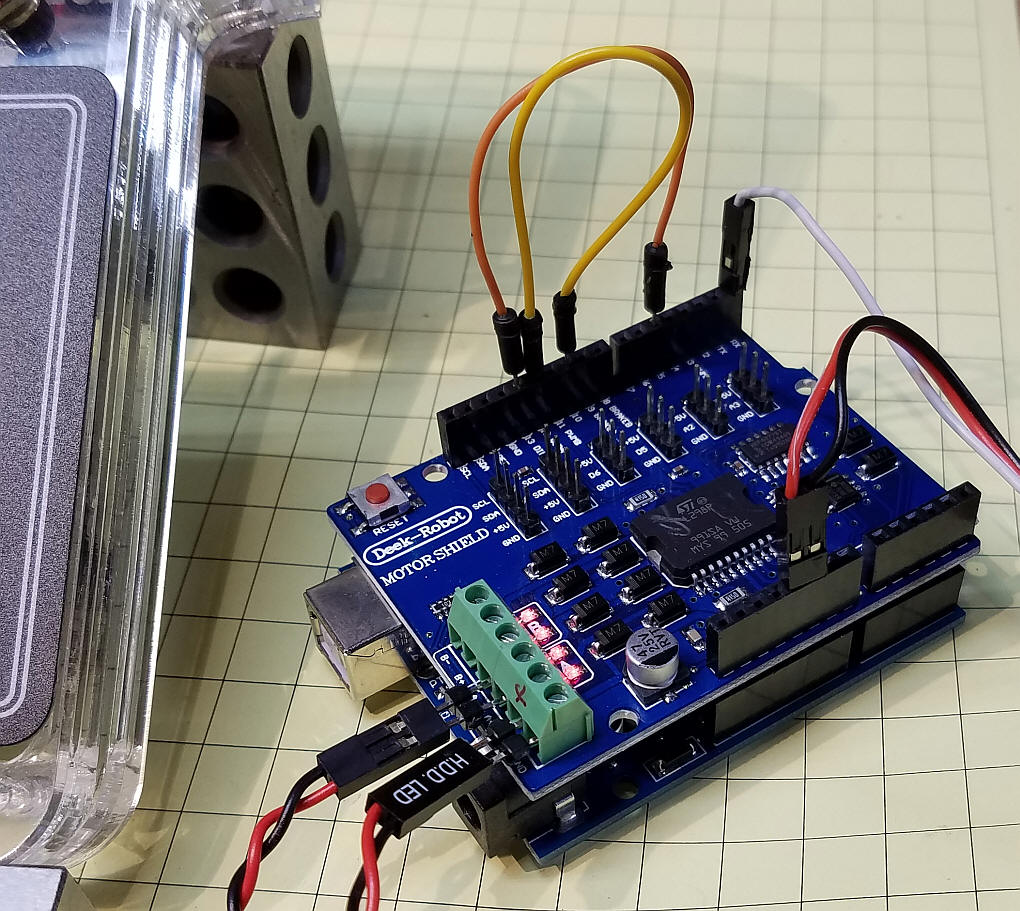
| The Circuit The schematic shows the parts that were used. There is no power supply shown as the throttle gets +5 volts from the DCC++ controller. The three wire cable that connects the throttle and the DCC++ controller carries ground, +5, and the transmit line from the serial port on the throttle. IMPORTANT NOTE: It seems that some keypads come with their internal wiring reversed. If you don't get the expected numbers when you wire the keypad as shown here try switching the wiring from end-to-end.
Here the three wires that come from the throttle connect to the DCC++ controller. The red and black are +5 and ground. The white wire goes to the RX terminal on the DCC++ controller.
|
||||
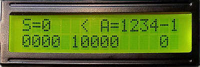
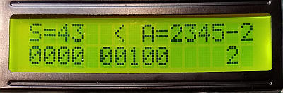
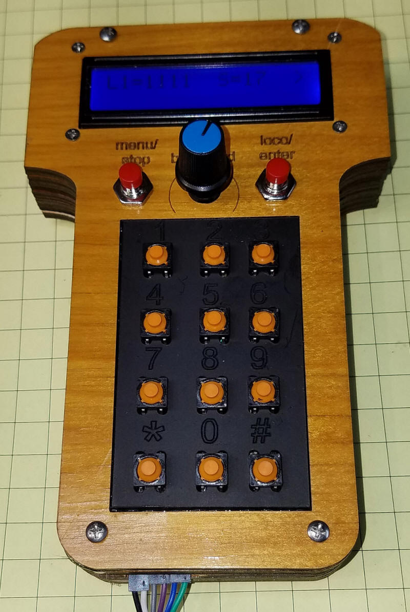
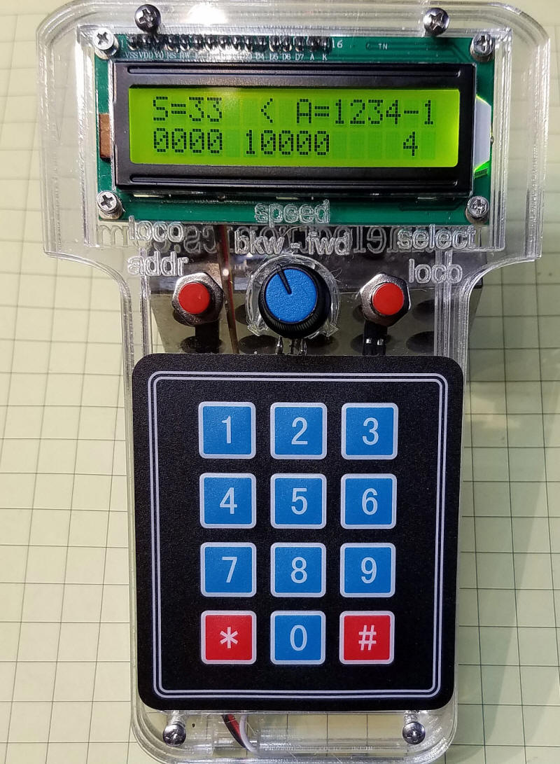
| Operation To use the throttle connect +5 and ground from the Arduino Pro Mini to the +5 and ground pins on the DCC++ controller. Connect the TX pin on the Pro Mini to the RX pin on the DCC++ controller. Turn on the power and you will see an introductory screen followed by one that looks something like this:
You can press the right button (labeled select loco) to select one of the 4 loco addresses that can be stored. In the photo above loco 1 has been chosen. Press the left button (labeled loco/addr) and you can enter the 4 digit loco address. Note that all 4 digits must be entered. For example for address 3 press 0 then 0 then 0 then 3.
Turn the potentiometer knob to the right (clockwise) to increase the speed forward and turn it left to increase the speed backwards. The center position stops the locomotive. This screen shows that the speed (S) is 43 and the direction (<) is backwards. The loco is #2 and its number is 2345
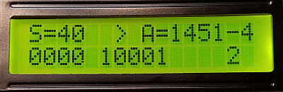
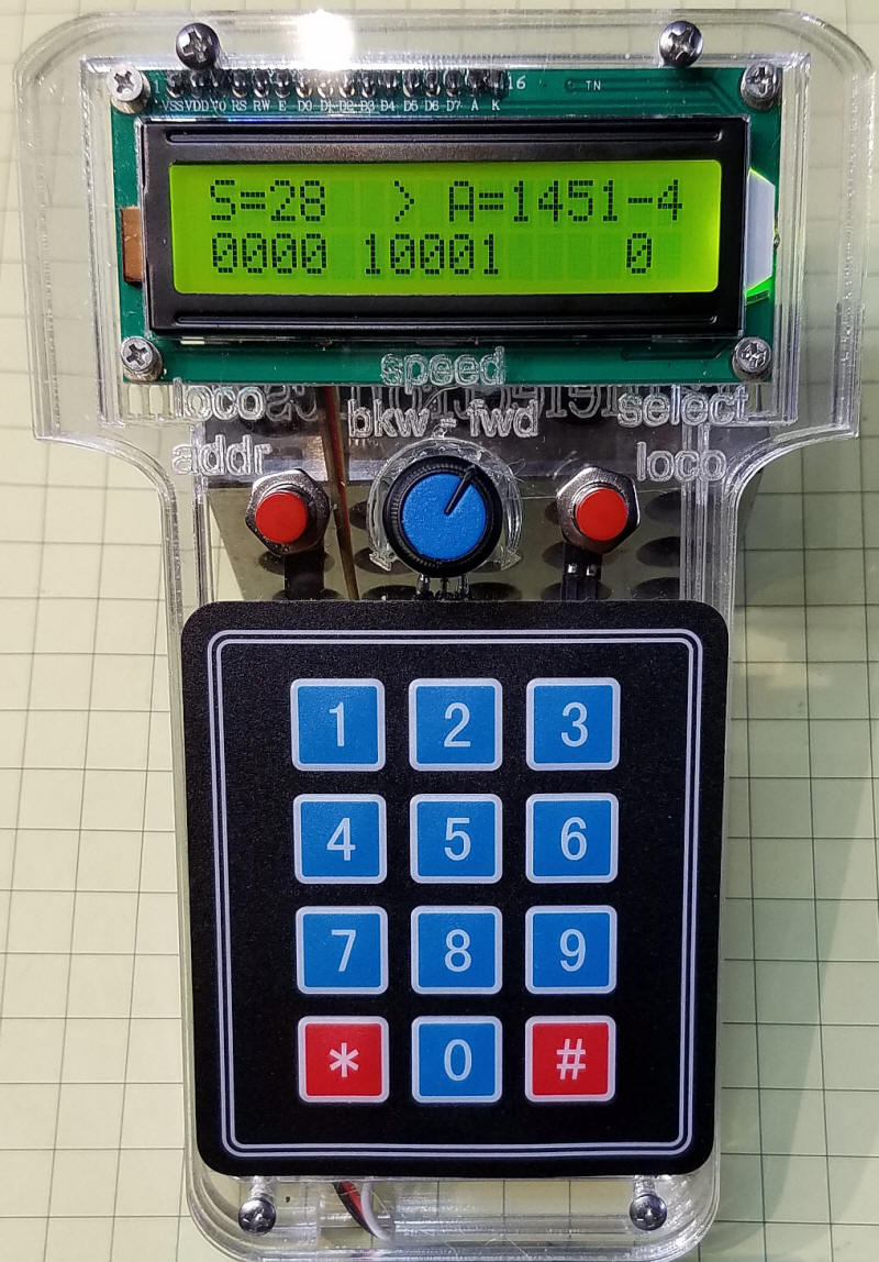
Here loco #4, with ID 1451, is going forward (>) at a speed or 40.
Pressing the "loco addr" button will shut the controller off stopping all trains. As soon as you start up a train with the potentiometer the power will be restored. |
||||
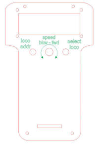
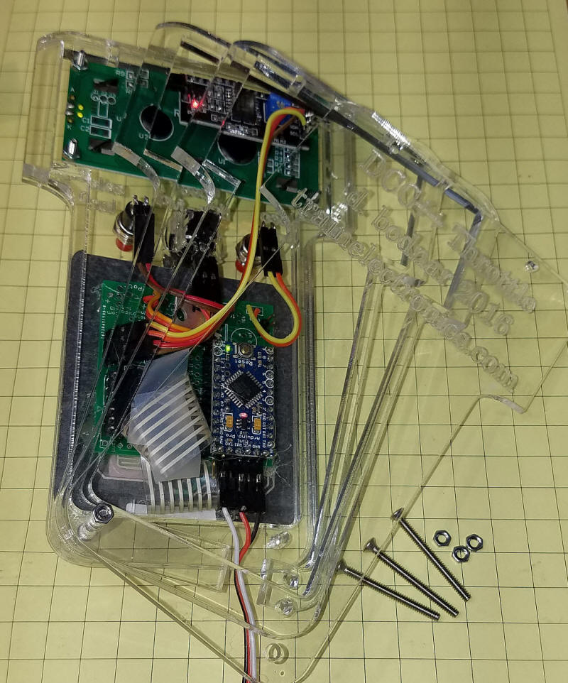
| Putting it Together This view shows the LCD panel, two switches and potentiometer before they are wired to the Arduino Pro Mini.
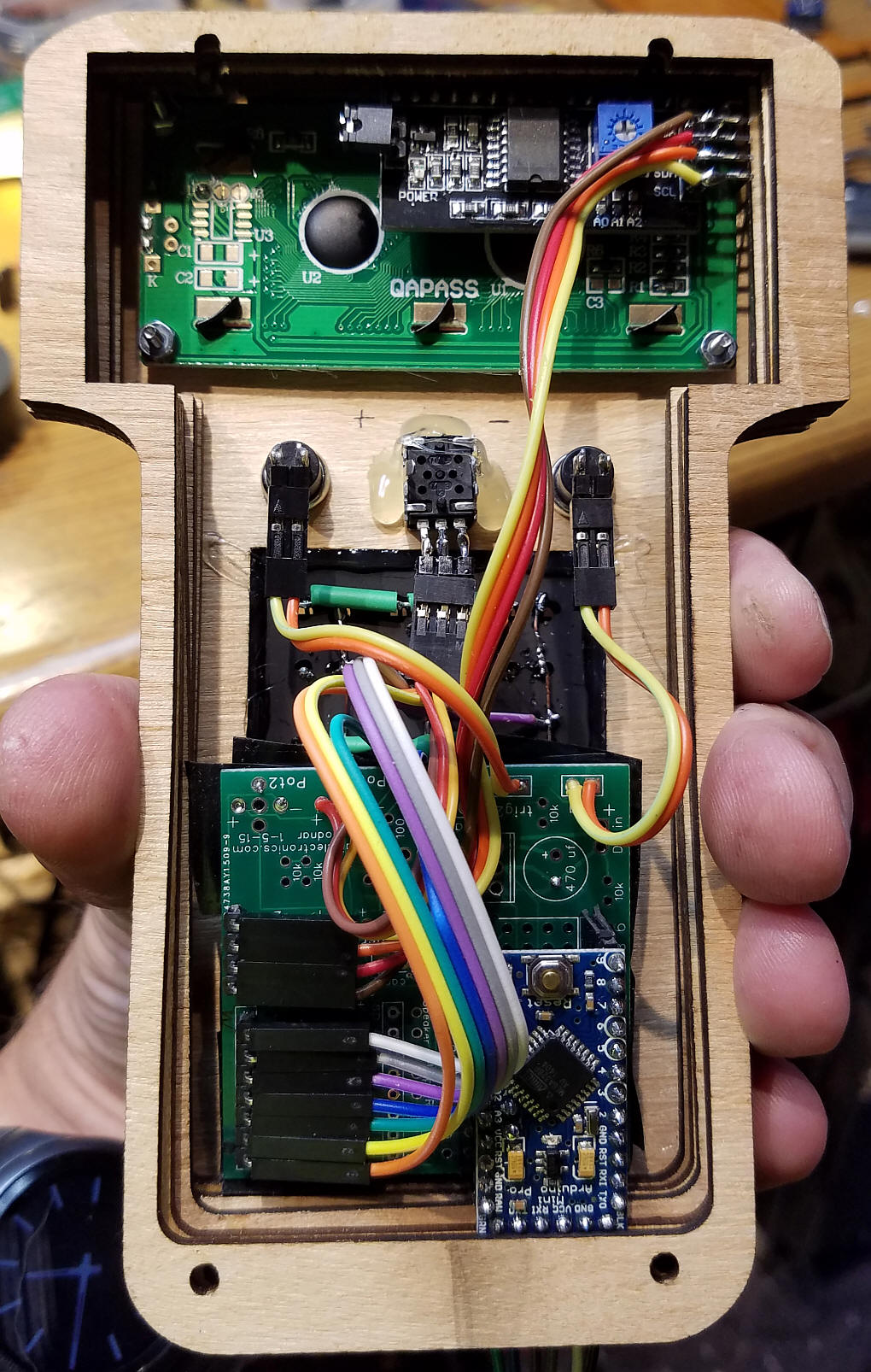
This interior view shows the wired prototype.
|
||||
|
The case for the two prototypes I have built were designed in CorelDraw and made with my laser cutter. There are three different pieces.
Here are the six pieces that I used for the acrylic case (front, back, four spacers). One spacer has a notch in it to allow the power/data cable to exit.
|
||||
| This is a prototype that I made from 1/8"
thick plywood.
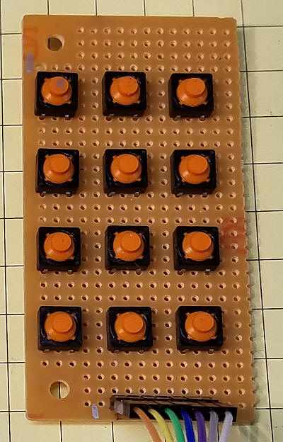
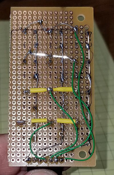
The keypad was made from a base plate of acrylic and 12 micro switches wired into a 3x4 matrix.
This view shows the wiring of the 3x4 matrix on the test keypad.
|
||||
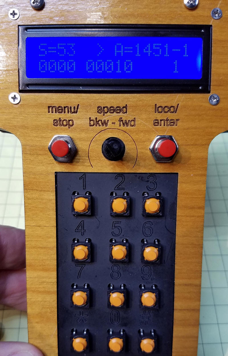
| The first prototype is shown here.
|
||||
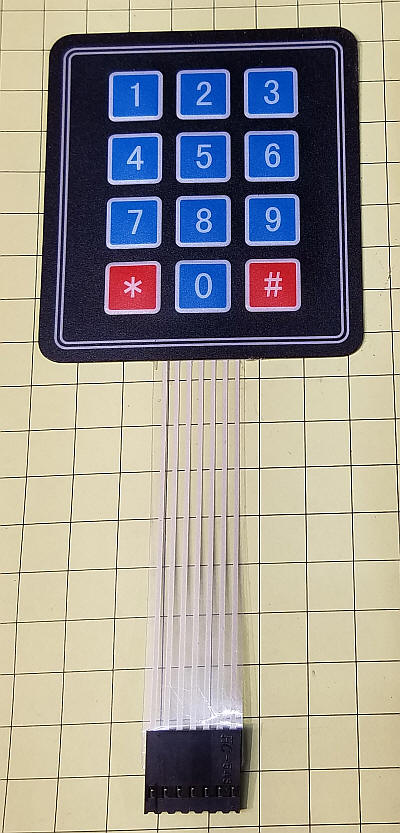
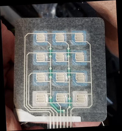
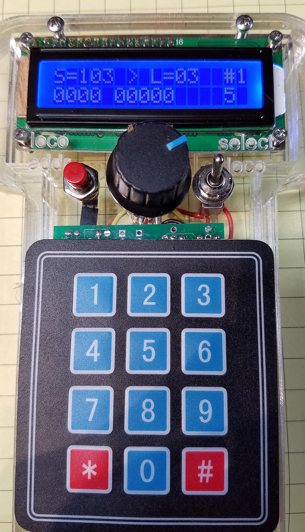
| The second prototype is shown here. It
uses a standard Arduino 3x4 matrix keypad.
|
||||
| Arduino Code The latest version of the software is below. Please note that it is currently under development and will change from time-to-time. It is also likely to have bugs! If you
have difficulty compiling you can try my set of libraries which are
available here: Code is here: DCC_Arduino/DCC++/Throttle/DCC_Throttle-lcd-pot-keypad--v1-7F2.ino DCC_Throttle-lcd-pot-keypad--v1-7F Note: Line #include "Arduino.h" Moved to top of code - some versions of the IDE may cause an error if it lower in the sketch.
/*
  VERSION WITH 3x4 KEYPAD, not capacitive touch unit
  Modified to use * and # in place of two buttons

  d. bodnar  revised 5-23-2016
   To Do:
   1.  LCD to show Loco #, speed, direction   L=5721 S=88 D=>    16 Characters
   2.  LCD line two Function display    0000 0000 0000 ?????
   3.  Left button calls up Menu
   4.  Right button used to change loco in focus
   5.  POT center = stop, CCW = reverse to max, CW = forward to max

*/
#include "Arduino.h"
byte Key;
#include<EEPROM.h>
char key ;
int LED = 13; // LED to blink when DCC packets are sent in loop
byte Fx = 0;
// Array set for 4 Loco2 - change the 7 numbers in the next 7 declarations
int maxLocos = 4;// number of loco addresses
int LocoAddress[4] = {1830, 3, 999, 4444};
int LocoDirection[4] = {1, 1, 1, 1};
int LocoSpeed[4] = {0, 0, 0, 0};
byte LocoFN0to4[4];
byte LocoFN5to8[4];
byte Locofn9to12[4];// 9-12 not yet implemented
int xxxxx = 0;
int pot1Pin = A3;
int potValue = 0;
int NewPotValue = 0;
int potValueOld = 0;
int counter = 0;
int Trigger1 = 3;
int Trigger2 = 4;
int TrigVal1 = 0;
int TrigVal2 = 0;
int old_speed = 0;
int ZeroSpeedFlag = 0;
int ActiveAddress = 0; // make address1 active
#include <Wire.h>
#include <LCD.h>
#include <LiquidCrystal_I2C.h>
#define I2C_ADDR    0x27 // <<----- Add your address here.  Find it from I2C Scanner
#define BACKLIGHT_PIN     3
#define En_pin  2
#define Rw_pin  1
#define Rs_pin  0
#define D4_pin  4
#define D5_pin  5
#define D6_pin  6
#define D7_pin  7
LiquidCrystal_I2C	lcd(I2C_ADDR, En_pin, Rw_pin, Rs_pin, D4_pin, D5_pin, D6_pin, D7_pin);
int z = 0;
int powerTemp = 0;
int i = 0;
char VersionNum[] = "1.7F "; ///////////////////////// //////////////////////VERSION HERE///////
#include <Keypad.h>
const byte ROWS = 4; //four rows
const byte COLS = 3; //three columns
char keys[ROWS][COLS] = {
  {'1', '2', '3'},
  {'4', '5', '6'},
  {'7', '8', '9'},
  {'*', '0', '#'}
};
byte rowPins[ROWS] = {5, 6, 7, 8 }; //{8,7,6,5 }; //connect to the row pinouts of the keypad
byte colPins[COLS] = {9, 10, 11}; // {11,10,9}; //connect to the column pinouts of the keypad
Keypad keypad = Keypad( makeKeymap(keys), rowPins, colPins, ROWS, COLS );
byte ledPin = 13;
boolean blink = false;
boolean ledPin_state;
int debug = 0; // set to 1 to show debug info on serial port - may cause issues with DCC++ depending on what is sent

void setup() {
  pinMode(Trigger1, INPUT);
  pinMode(Trigger2, INPUT);
  digitalWrite(Trigger1, HIGH);// turn on pullup resistors
  digitalWrite(Trigger2, HIGH);// turn on pullup resistors
  // randomSeed(analogRead(0));
  pinMode(LED, OUTPUT);
  lcd.begin (16, 2); //  LCD is 16 characters x 2 lines
  lcd.setBacklightPin(BACKLIGHT_PIN, POSITIVE);
  lcd.setBacklight(HIGH);  // Switch on the backlight
  lcd.home (); // go home
  Serial.begin (115200);
  lcd.setCursor(0, 0);
  lcd.print("DCC++ Throttle");
  lcd.setCursor(0, 1);
  lcd.print("5-26-16 - v");
  for (int i = 0; i < 4; i++) {
    lcd.print(VersionNum[i]);
    //delay(500);
  }
  getAddresses();  // read eeprom
  Serial.print("5-22-2016  version ");
  for (int i = 0; i < 4; i++) {
    Serial.print(VersionNum[i]);
    //delay(500);
  }
  if (debug == 1) Serial.println("");
  Serial.print("<0>");// power off to DCC++ unit
  delay(1500);

  pinMode(ledPin, OUTPUT);              // Sets the digital pin as output.
  digitalWrite(ledPin, HIGH);           // Turn the LED on.
  ledPin_state = digitalRead(ledPin);   // Store initial LED state. HIGH when LED is on.
  keypad.addEventListener(keypadEvent); // Add an event listener for this keypad

  // showFirstLine();
  lcd.clear();

}  // END SETUP

void loop() {
  TrigVal1 = digitalRead(Trigger1);   // read the input pin
  TrigVal2 = digitalRead(Trigger2);   // read the input pin
  key = keypad.getKey();
  // if (key) {
  if (key == 42) { // *
    all2ZeroSpeeed();
    getLocoAddress();
    key = 0;
  }
  // }
  if (TrigVal1 == 0) {
    all2ZeroSpeeed();
    getLocoAddress();
    //   showFirstLine();
  }
  potValue = analogRead(pot1Pin);    // read the value from the sensor
  if (potValue != potValueOld) {
    NewPotValue = 1;
    //doMainLCD();
  }
  else NewPotValue = 0;
  potValueOld = potValue;
  potValue = (potValue / 4) - 128;
  if (potValue <= 0) {
    LocoDirection[ActiveAddress] = 0; // backward
  }
  else LocoDirection[ActiveAddress] = 1; // forward
  potValue = abs(potValue);
  if (potValue >= 126) potValue = 126; // max is 127
  if (potValue <= 3) potValue = 0; // set to zero if close to zero
  LocoSpeed[ActiveAddress] =   potValue;
  if (NewPotValue == 1) {
    doDCC();
    doMainLCD();
    NewPotValue = 0;
    delay(50);
  }
  if (key == 35) { // #
    ActiveAddress++;
    if (ActiveAddress >= 4) ActiveAddress = 0;
    //showFirstLine();
    doMainLCD();
    delay(200);
    key = 0;
  }
  if (TrigVal2 == 0) {   // change loco # on right button press
    ActiveAddress++;
    if (ActiveAddress >= 4) ActiveAddress = 0;
    //showFirstLine();
    doMainLCD();
    delay(200);
  }
  //  key = keypad.getKey();
  //    Serial.print("KKKKKKKKKKKKKKKKKEY =");
  //    Serial.println(key);
  if (key != 42 && key != 35 && key >= 40) {
    //   if (key == 42) Serial.println("****************************");
    //   Serial.print("KEY =");
    //   Serial.println(key);
    doFunction();
  }
  // doMainLCD();
}  //END LOOP


//START DO FUNCTION BUTTONS
int doFunction() {
  key = key - 48 - 1; // convert from ascii value
  lcd.setCursor (14, 1);       // go to end of 2nd line
  ///  lcd.print("FN code ");
  lcd.print(key, DEC);
  if (debug == 1) Serial.print("got a keypad button ");
  if (debug == 1) Serial.println(key, DEC);
  if (key <= 4) {
    if (bitRead(LocoFN0to4[ActiveAddress], key) == 0 ) {
      bitWrite(LocoFN0to4[ActiveAddress], key, 1);
    }
    else {
      if (bitRead(LocoFN0to4[ActiveAddress], key) == 1 ) {
        bitWrite(LocoFN0to4[ActiveAddress], key, 0);
      }
    }
    doDCCfunction04();
    Serial.print(LocoFN0to4[ActiveAddress], BIN);
    if (debug == 1) Serial.println(" LocoFN0to4[ActiveAddress] d ");
    Serial.print(LocoFN0to4[ActiveAddress], DEC);
    if (debug == 1) Serial.println(" LocoFN0to4[ActiveAddress]");
  }
  if (key >= 5 && key <= 8) {
    key = key - 5;
    if (bitRead(LocoFN5to8[ActiveAddress], key) == 0 ) {
      bitWrite(LocoFN5to8[ActiveAddress], key, 1);
    }
    else {
      if (bitRead(LocoFN5to8[ActiveAddress], key) == 1 ) {
        bitWrite(LocoFN5to8[ActiveAddress], key, 0);
      }
    }
    doDCCfunction58();
    Serial.print(LocoFN5to8[ActiveAddress], BIN);
    if (debug == 1) Serial.println(" LocoFN5to8[ActiveAddress] d ");
    Serial.print(LocoFN5to8[ActiveAddress], DEC);
    if (debug == 1) Serial.println(" LocoFN5to8[ActiveAddress]");
  }
  if (key == -1)
  {
    lcd.setCursor (14, 1);       // go to end of 2nd line
    ///    lcd.print("FN code ");
    lcd.print(key, DEC);
    key = 0;
    LocoFN0to4[ActiveAddress] = B00000000; //clear variables for which functions are set
    LocoFN5to8[ActiveAddress] = B00000000;
    doDCCfunction04();
    doDCCfunction58();
    delay(500);
    key = 0;
  }
  key = 0;
  // delay(500);
  doMainLCD();
}
//END DO FUNCTION BUTTONS

void showFirstLine() {
  // break;
  if (debug == 1) Serial.println(" ");
  lcd.setCursor(0, 0);
  lcd.print("                ");// clear
  lcd.setCursor(0, 0);
  lcd.print("L");
  lcd.print(ActiveAddress + 1);
  lcd.print("=");
  lcd.print(LocoAddress[ActiveAddress]);

  for (int zzz = 0; zzz <= 3; zzz++) {
    if (debug == 1) Serial.print("add # ");
    if (debug == 1) Serial.print(zzz + 1);
    if (debug == 1) Serial.print(" ");
    if (debug == 1) Serial.println(LocoAddress[zzz]);

  }


}

void getLocoAddress() {
  Serial.print("<0>");// power off to DCC++ unit
  int total = 0;
  counter = 0;
  lcd.clear();
  lcd.setCursor(0, 0);
  lcd.print("Set Dcc Addr # ");
  lcd.print(ActiveAddress + 1);
  if (debug == 1) Serial.println(" @ top");
  do {
    TrigVal2 = digitalRead(Trigger2);   // read the input pin
    if (TrigVal2 == 0) break; // exit routine if right button pressed - ABORT new address
    key = keypad.getKey();
    if (key) {
      counter++;
      int number =  key - 48;
      total = total * 10 + number;
      if (debug == 1) Serial.print("TOTAL= ");
      if (debug == 1) Serial.println(total);
      lcd.setCursor(0, 1);
      if (total == 0) {   // print multiple zeros for leading zero number
        for (int tempx = 1; tempx <= counter; tempx++) {
          lcd.print("0");
        }
      }
      else lcd.print(total);
      if (debug == 1) Serial.print("Counter = ");
      if (debug == 1) Serial.print(counter);
      if (debug == 1) Serial.print("  key= ");
      if (debug == 1) Serial.print(key);

      if (debug == 1) Serial.print("   val =");
      if (debug == 1) Serial.println(number);
    }
    TrigVal2 = digitalRead(Trigger2);   // read the input pin
  }
  while (counter <= 3); //  collect exactly 4 digits
  //  while (  TrigVal2 == 1);
  LocoAddress[ActiveAddress] = total;
  saveAddresses();
  lcd.clear();
  doMainLCD();
}


// Taking care of some special events.
void keypadEvent(KeypadEvent key) {
  switch (keypad.getState()) {
    case PRESSED:
      if (key == '#') {
        digitalWrite(ledPin, !digitalRead(ledPin));
        ledPin_state = digitalRead(ledPin);        // Remember LED state, lit or unlit.
      }
      break;

    case RELEASED:
      if (key == '*') {
        digitalWrite(ledPin, ledPin_state);   // Restore LED state from before it started blinking.
        blink = false;
      }
      break;

    case HOLD:
      if (key == '*') {
        blink = true;    // Blink the LED when holding the * key.
      }
      break;
  }
}


void doDCC() {
  //Serial.print("d = ");
  if (debug == 1) Serial.println(LocoDirection[ActiveAddress] );
  Serial.print("<1>");
  Serial.print("<t1 ");
  Serial.print(LocoAddress[ActiveAddress] );//locoID);
  Serial.print(" ");
  Serial.print(LocoSpeed[ActiveAddress] );
  Serial.print(" ");
  Serial.print(LocoDirection[ActiveAddress] );
  Serial.write(">");
}

void doDCCfunction04() {
  Serial.write("<f ");
  Serial.print(LocoAddress[ActiveAddress] );
  Serial.print(" ");
  int fx = LocoFN0to4[ActiveAddress] + 128;
  Serial.print(fx);
  Serial.print(" >");
}

void doDCCfunction58() {
  Serial.write("<f ");
  Serial.print(LocoAddress[ActiveAddress] );
  Serial.print(" ");
  int fx = LocoFN5to8[ActiveAddress] + 176;
  Serial.print(fx);
  Serial.print(" >");
}

void all2ZeroSpeeed() {  // set flag to 1 to stop, set to 0 to restore
  for (int tempx = 0; tempx <= maxLocos; tempx++) {
    Serial.print("<t1 ");
    Serial.print(LocoAddress[tempx] );//locoID);
    Serial.print(" ");
    if (ZeroSpeedFlag == 1) {
      Serial.print(0);//LocoSpeed[0] );
    }
    else Serial.print(LocoSpeed[0] );
    Serial.print(" ");
    Serial.print(LocoDirection[1] );
    Serial.write(">");
  }
}

void getAddresses() {
  int xxx = 0;
  for (int xyz = 0; xyz <= maxLocos - 1; xyz++) {
    LocoAddress[xyz] = EEPROM.read(xyz * 2) * 256;
    LocoAddress[xyz] = LocoAddress[xyz] + EEPROM.read(xyz * 2 + 1);
    if (LocoAddress[xyz] >= 10000) LocoAddress[xyz] = 3;

    if (debug == 1) Serial.println(" ");
    if (debug == 1) Serial.print("loco = ");
    if (debug == 1) Serial.print(LocoAddress[xyz]);
    if (debug == 1) Serial.print("  address# = ");
    if (debug == 1) Serial.print(xyz + 1);
  }
  if (debug == 1) Serial.println(" ");
}

void saveAddresses() {
  int xxx = 0;
  for (int xyz = 0; xyz <= maxLocos - 1; xyz++) {
    xxx = LocoAddress[xyz] / 256;
    if (debug == 1) Serial.println(" ");
    if (debug == 1) Serial.print("loco = ");
    if (debug == 1) Serial.print(LocoAddress[xyz]);
    if (debug == 1) Serial.print("  address# = ");
    if (debug == 1) Serial.print(xyz);
    if (debug == 1) Serial.print(" msb ");
    if (debug == 1) Serial.print(xxx);
    if (debug == 1) Serial.print(" writing to ");
    if (debug == 1) Serial.print(xyz * 2);
    if (debug == 1) Serial.print(" and ");
    if (debug == 1) Serial.print(xyz * 2 + 1);
    EEPROM.write(xyz * 2, xxx);
    xxx = LocoAddress[xyz] - (xxx * 256);
    if (debug == 1) Serial.print(" lsb ");
    if (debug == 1) Serial.print(xxx);
    EEPROM.write(xyz * 2 + 1, xxx);
  }
}


void doMainLCD() {
  //lcd.setCursor(0, 0);
  //lcd.print("               ");
  lcd.setCursor(0, 0);
  lcd.print("S=");
  lcd.print(LocoSpeed[ActiveAddress], DEC);
  lcd.print("  ");
  lcd.setCursor(6, 0);
  if (LocoDirection[ActiveAddress] == 1 ) {
    lcd.print(">");
  }
  else {
    lcd.print("<");
  }

  lcd.setCursor(8, 0);

  lcd.print("L=");
  if (LocoAddress[ActiveAddress] <= 9) {
    lcd.print("0");  // add leading zero for single digit addresses
  }
  lcd.print(LocoAddress[ActiveAddress] , DEC);
  lcd.print("   ");
  lcd.setCursor(14, 0);
  lcd.print("#");
  lcd.setCursor (15, 0);       // go to end of 1st line
  lcd.print(ActiveAddress + 1);
  lcd.setCursor(5, 1); // start of 2nd line
  String temp = "0000" + String(LocoFN0to4[ActiveAddress], BIN);  // pad with leading zeros
  int tlen = temp.length() - 5;
  lcd.print(temp.substring(tlen));
  temp = "000" + String(LocoFN5to8[ActiveAddress], BIN);
  tlen = temp.length() - 4;
  lcd.setCursor(0, 1); // start of 2nd line
  lcd.print(temp.substring(tlen));

}
|
||||
| Wireless Option
The throttle works very well with a 3 wire cable connection between it and the DCC++ unit. You will recall that these three wires carry 5 volts DC, ground and the serial data that goes from the throttle TX pin to the DCC++ RX pin. To make the unit wireless several changes have to be made.
|
||||
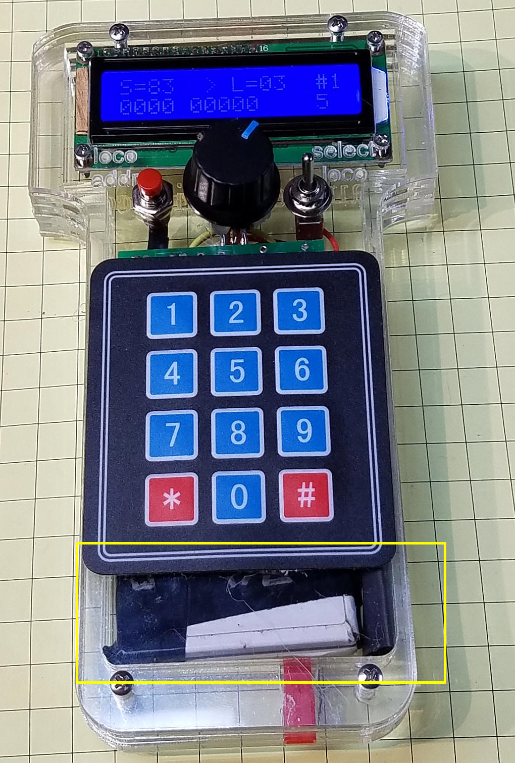
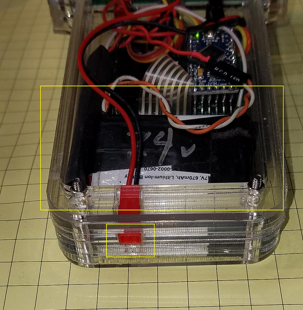
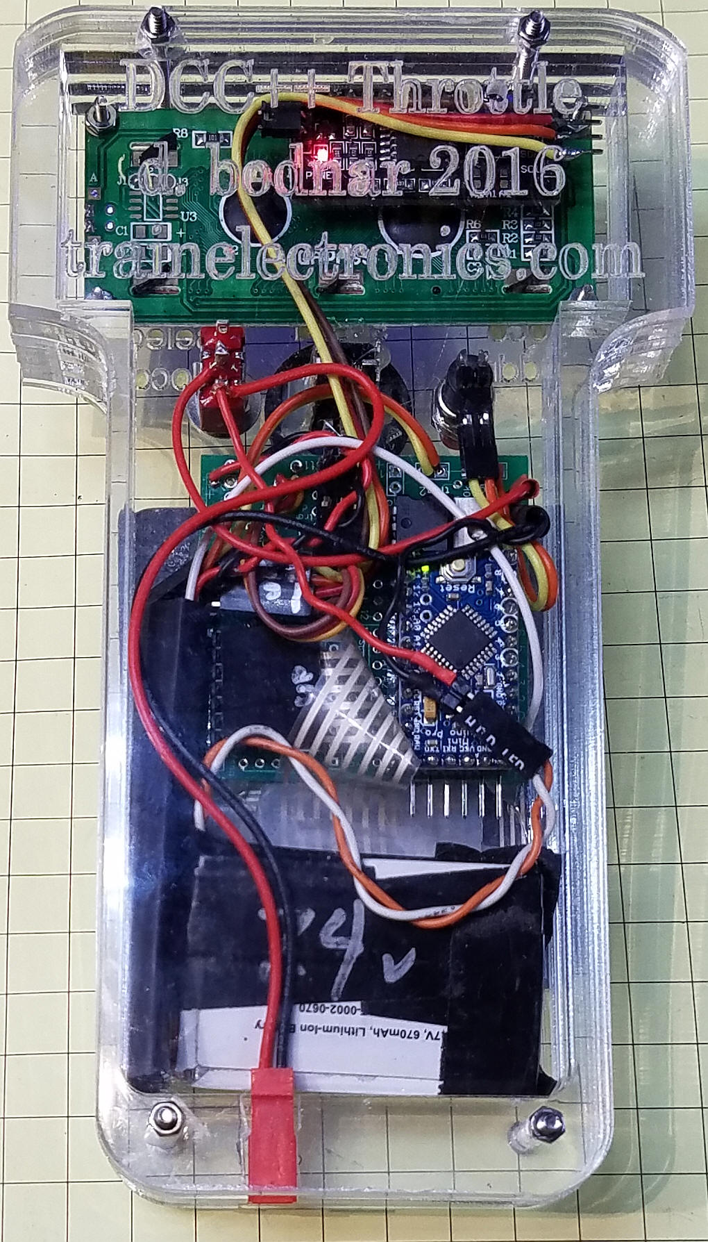
 This photo shows the battery at the bottom of the case. You can also see the red JST connector that is used to charge the battery.
This back view shows the full battery and the JST connector.
The full back view clearly shows all of the components.
|
||||
|
|
||||
| Wiring for Wireless The batteries I am using have an internal charging circuit as do most cell phone batteries. This allows the simplest of charging circuits. I just send power (about 9 volts for a 7.2 volt battery) to the positive and negative terminals on the battery. When the battery is charged it automatically stops charging. A voltage regulator has been added to the circuit to drop the battery voltage to 5 volts for the throttle. The only other change is connecting the HC-12 RX pin to the Arduino TX pin. You need to add the other HC-12 to the DCC++ unit connecting it to +5 volts, ground and wiring its TX pin to the DCC++ Arduino's RX pin. SIMPLE!
|
||||
| Parts The parts list is below.
|
||||
|
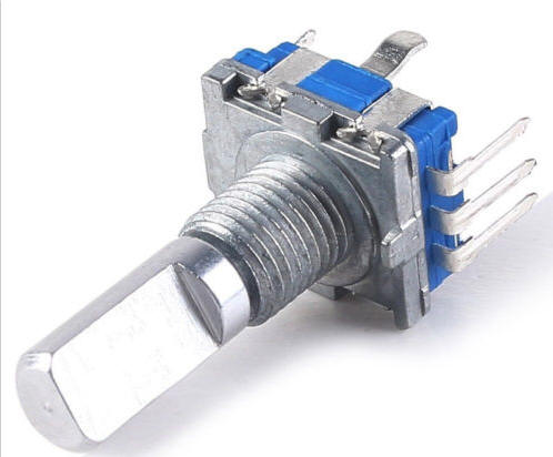
Rotary Encoder in
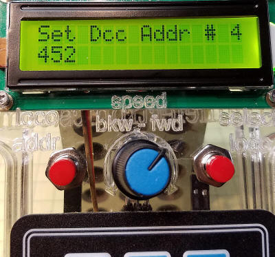
place of Potentiometer Some model railroaders prefer a rotary encoder over the potentiometer that is used in the above throttle. This requires modification to the hardware and software. The schematic shown below includes a rotary encoder that has a pushbutton switch built in. The three pins shown in the photo are for the encoder. There are two more pins on the other side for the button.
You turn the knob on the encoder clockwise or counter clockwise to change speed up or down and push the knob in to change direction. Note that the pushbutton part of the encoder includes a 10k pull-up resistor. Make sure you use this rather than using the Arduino's capability of pulling a pin up internally. That option does not work reliably while the 10k pull-up does work very well. |
||||
| This schematic shows the wireless HC-12 units
but the rotary encoder version of this throttle will work equally well
when hard wired to the DCC++ controller. The two 0.1 uf caps (C3
and C4) help to debounce the signal from the encoder. They go
between the outer pins and the center pin (ground).
|
||||
| An Unexpected Event While using the wireless version of the throttle I discovered that the HC-12 transceiver pairs appear to have an internal configuration that allows the receiver attached to the DCC++ unit to receive transmitted packets from two different throttles without any interference or parsing errors. This behavior was quite unexpected but turns out to be a welcome thing! This allows two throttles to control different trains on the same track at the same time. I have not tried using 3 or more throttles but will once I build up additional throttles. |
||||
| Software Changes in this Version The throttle can handle up to 4 engines. Pressing the # button changes the locomotive that is being controlled. If you are using only 2 locomotives it can become tedious to press the # button several extra times to skip over the unused locomotive addresses. To eliminate this problem you can change the number of locomotives that the throttle will control to 4, 3, 2 or 1. To make this change press the button on the rotary encoder when turning on the throttle. You will be shown the number of active addresses and will be asked to press 1, 2, 3 or 4 on the keypad to set the new number of locomotives. The number of active addresses that you choose will be stored in the throttle and will be kept until you change it. The maximum speed is limited to 126. If you need to change this up or down you can change the value in this line - it is at about line 222 in the sketch. encoderPos = constrain(encoderPos, 0, 126);
|
||||
| Arduino Code for Rotary Encoder The code is fairly complete but is sure to be updated after more testing. If you have difficulty compiling
you can try my set of libraries which are available here: DCC_Throttle-lcd-RotaryEncoder-keypad--v2-6a -- version that allows you to set maximum number of locos (1-4) Note: Line
#include "Arduino.h"
Moved to top of code - some versions of the IDE may cause an
error if it is lower in the sketch. |
||||
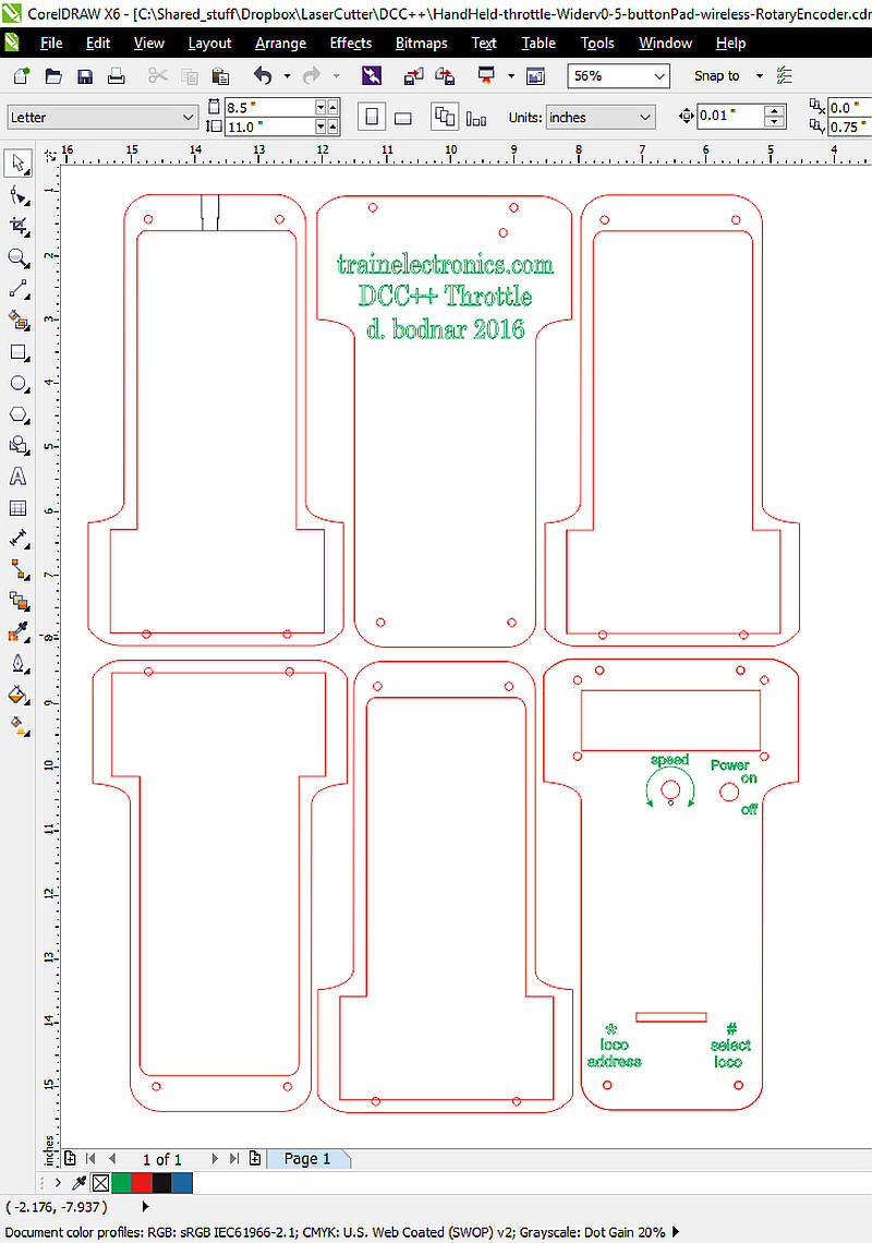
| This is the CorelDraw file that is used to
make the case. The front (bottom right), back (top center) and
cutout for the power plug (top left) are made from 1/8" Plexiglas and
the other three sections are made from 1/4" Plex. You can download
the file here:
DCC_Arduino/DCC++/Throttle/Throttle-encoder-wireless.cdr
|
||||
| Building from a Modified Circuit Board The throttles shown above were built on a circuit board that was designed for an MP3 player that was controlled by the Arduino Pro Mini. With some minor change it fits the throttle nicely.
|
||||
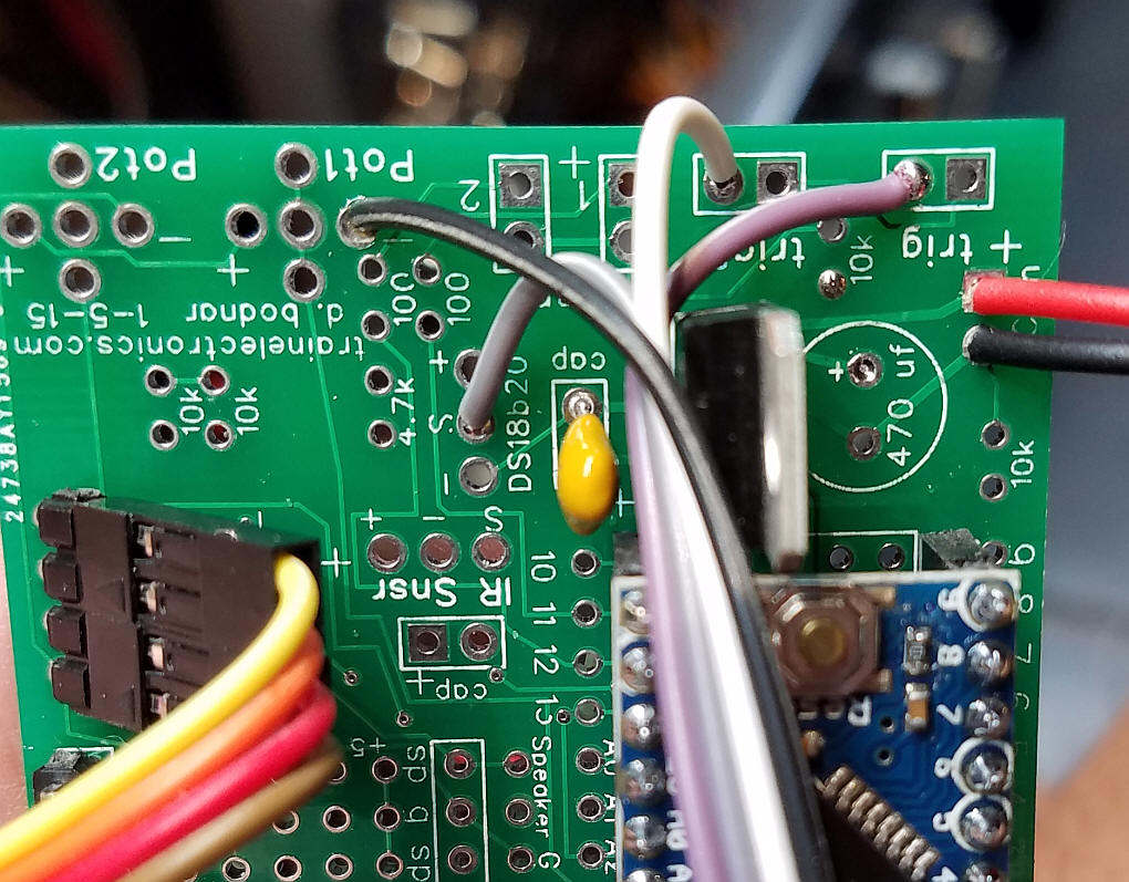
| The LCD connects to pins A4 and A5 which have
to be accessed by a 2 pin header as is shown circled in yellow. A
matching pair of pins are soldered to the bottom of the Arduino
|
||||
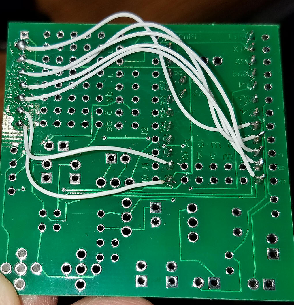
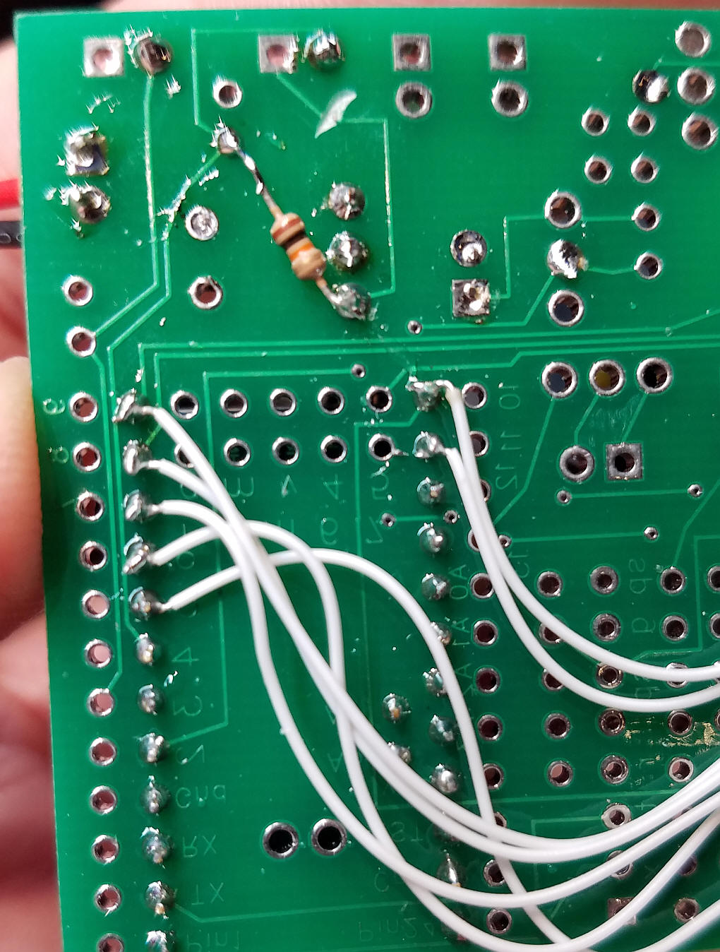
| The wiring for the keypad is shown here.
The schematic shows the pin numbers.
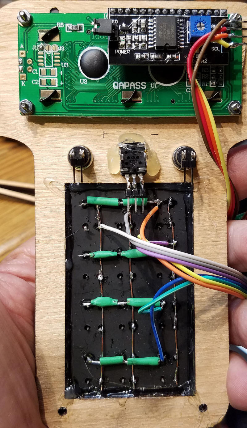
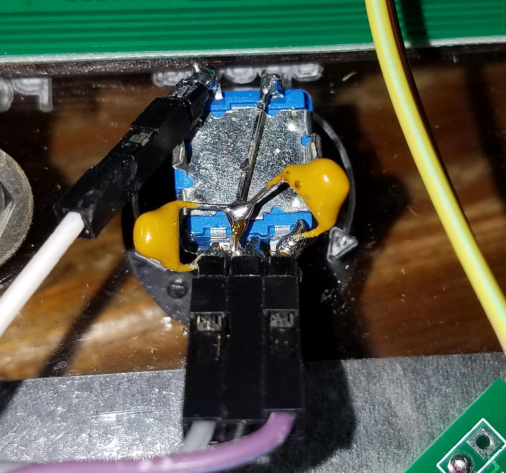
The encoder and its button connect as shown here. The four wires to the left go to the LCD.
The wiring for the encoder includes two 0.1 uF caps each wired to an encoder data pin and ground. If you prefer these can be added to the circuit board. One pin of the button (the top two pins) goes to the board (white wire) while the other goes to ground (center pin on the 3 pin end of the encoder)
A 10K resistor goes on the board as shown. It pulls the button on the encoder high. Note the cut trace at top, center.
|