| The third Fidget Spinner video that I posted (see link above) has an objective of getting the rotation of the spinner up to 5000 revolutions per minute. In order to determine if that happened I wanted to have a tachometer that gave reliable and repeatable results. |
| Measure Speed of Rotation In order to measure the speed of rotation I used both a frequency counter and an oscilloscope. I connected to the circuit's ground and the output of the IR sensor to these devices. The measured frequency was three times the number of rotations per second since the sensor was detecting three lobes going by for each rotation. To convert this to revolutions per minute (RPM) I just divided the frequency by three then multiplied that result by 60. Or you can just multiply the frequency by 20 since dividing a number by three then multiplying by 60 is the same as multiplying by 20. |
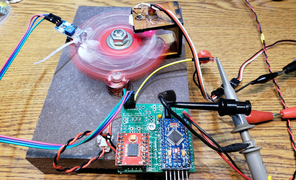
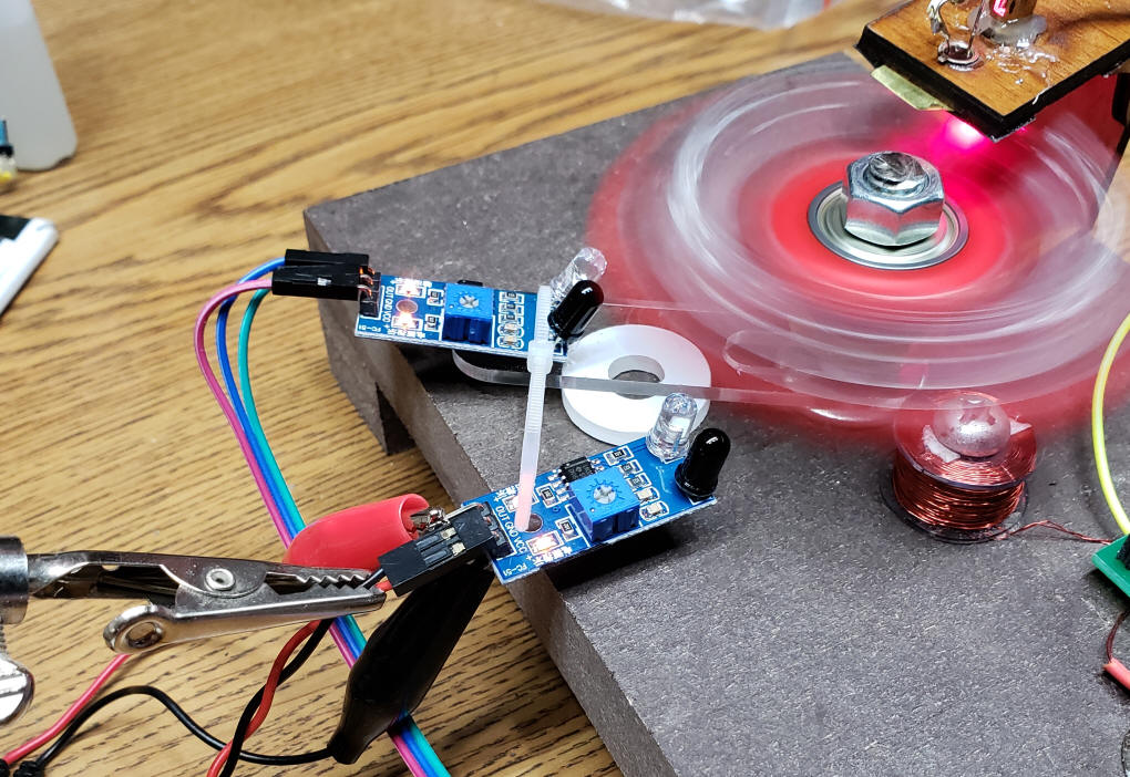
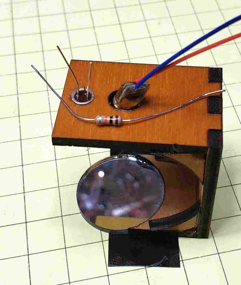
| Measurement Setup This image shows the one coil fidget spinner motor with the IR sensor that is connected to the Arduino. This setup was discussed on this web page Fidget Spinner Motors and on video #3 For this speed test I connected both a multimeter with a frequency measurement capability and two oscilloscopes to the output pin on the IR sensor. These connections go to the yellow wire that comes off of the Arduino board. The meter and scope were also connected to ground (the black wires that clip onto the top of the voltage regulator)
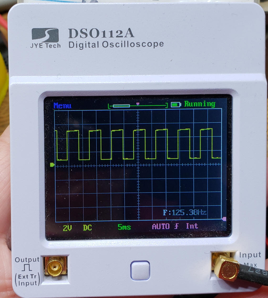
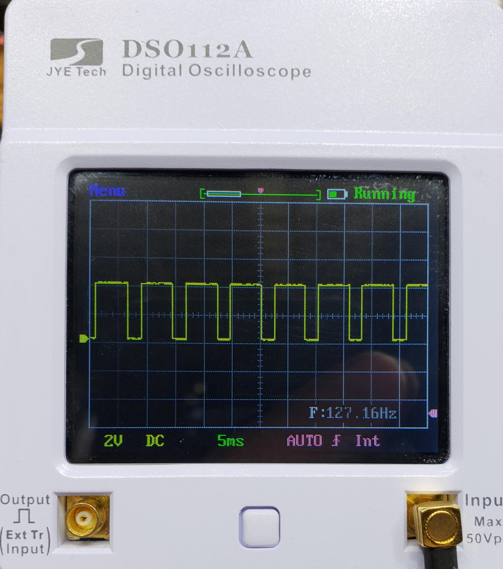
The first scope is shown here. Note the square wave pulses and the frequency (125.38) on the screen. If we multiply the frequency times 20 we get a rotational value of a bit over 2500 rpm.
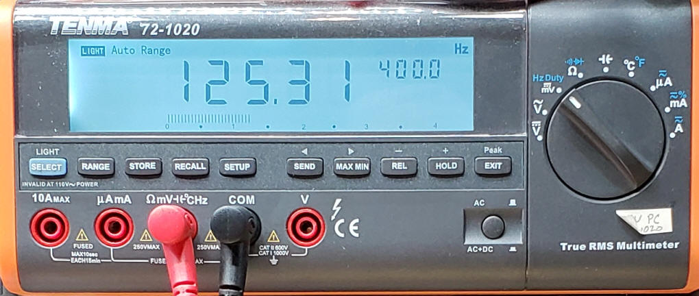
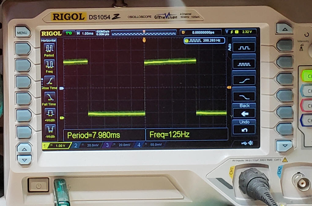
The multimeter shows almost the same frequency, 125.31. My large scope also shows the square wave pulses and the same frequency.
To get a reading from a device that is not physically connected to the fidget spinner circuit I applied 5 volts to another IR sensor board and connected the scopes and meter to the output pin. In this photo you can see the second IR sensor being held just under the fidget spinner.
The wave is slightly different, due to the placement of the IR sensor. The frequency has also increased a bit, probably due to the bearing warming up.
|
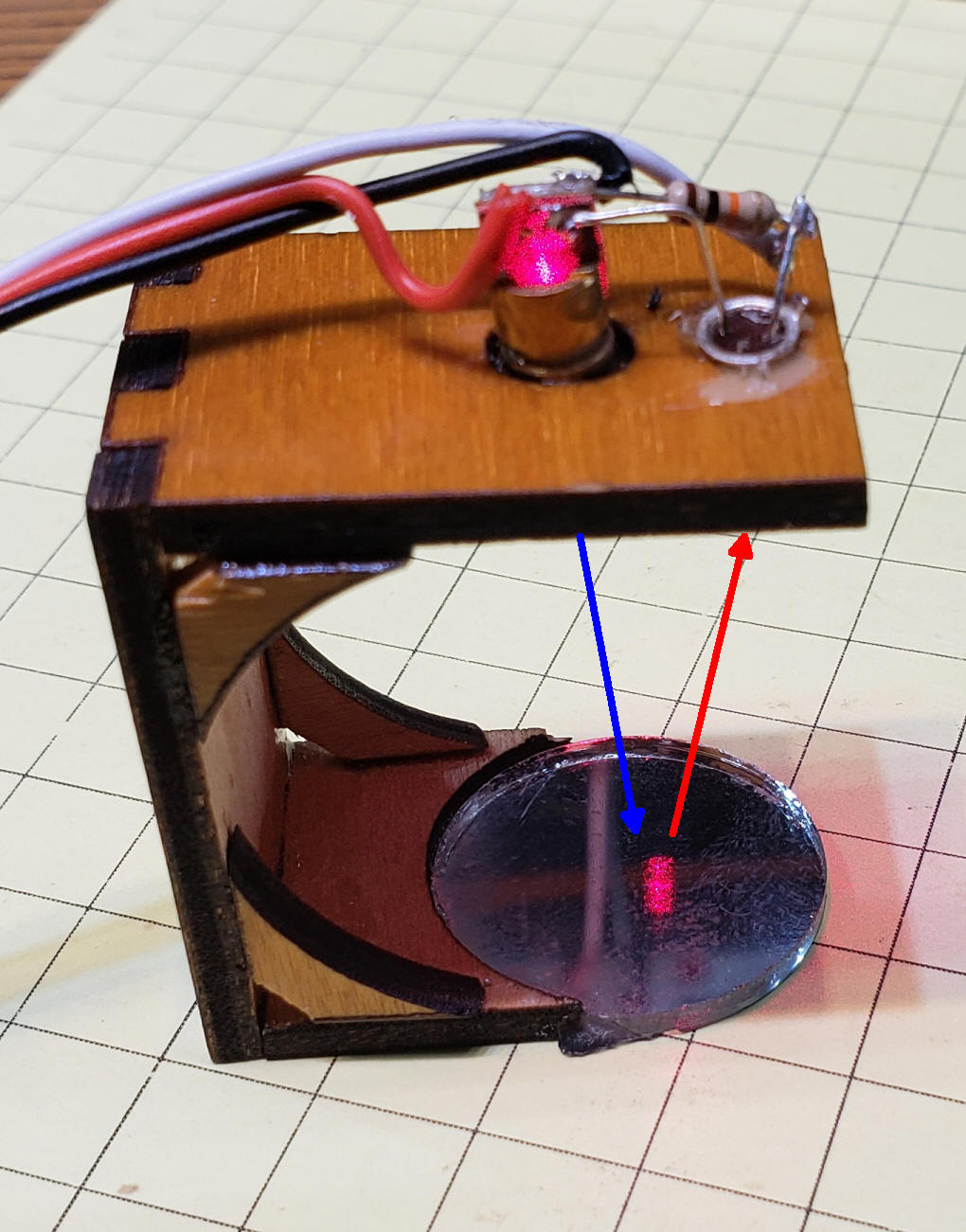
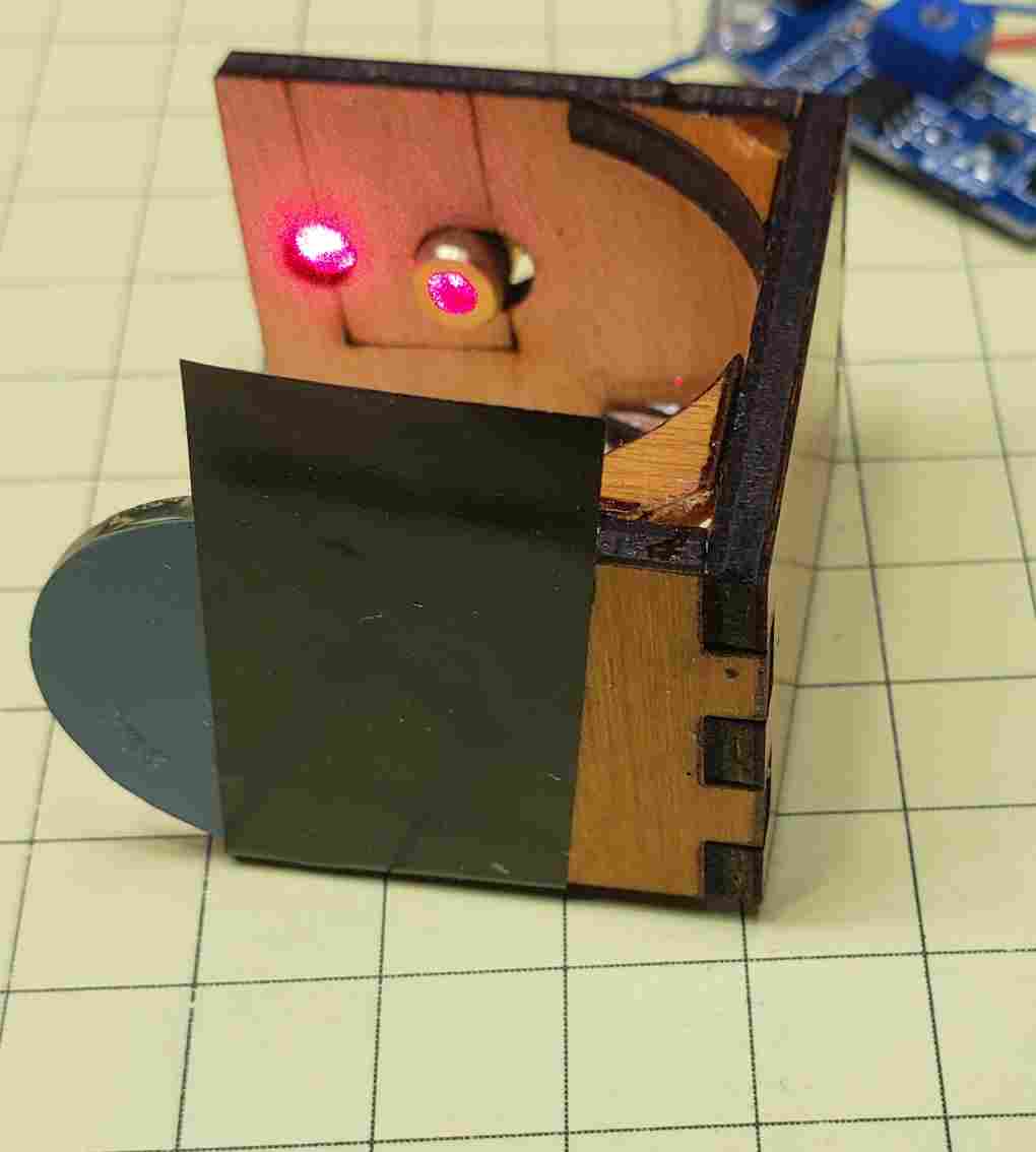
The Tachometer This photo shows the laser sensor. The blue arrow represents the laser beam as it goes to the mirror and the red arrow represents it reflecting off of the mirror and onto the phototransistor.
|
| Tachometer Hardware The hardware is composed of an Arduino Pro Mini (Amazon eBay), a phototransistor, I prefer the ones in a metal can, ( Amazon eBay), a laser diode (Amazon eBay) and a 10K resistor. In addition I added a 2 line LCD display with I2C interface to show the results (Amazon eBay). Connect the laser sensor and phototransistor as shown. The output of the IR sensor would also connect to pin #2 on the Arduino. The schematic is here:
|
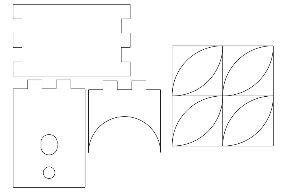
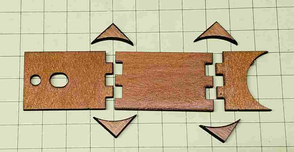
| Tachometer Sensor I wanted a sensor that I could move around the motor so I built up a base that used a small mirror to reflect the laser beam from the small laser to the phototransistor, both of which were mounted a the top of the unit. The pieces shown here were cut from 1/8" plywood. The laser goes into the oblong hole and the phototransistor into the round hole. When gluing them together make sure that the top and bottom are parallel. Attach the small mirror to the bottom piece. Glue in the phototransistor first then the laser, adjusting its position so that the laser beam reflects into the enter of the phototransistor. My first sensor was somewhat intermittent. I found that masking off most of the phototransistor made a dramatic difference, probably by blocking light from the room from entering it. I used a thin piece of brass sheet (paper thin) with a small hole poked into it to cover most of the phototransistor. Aluminum foil will work, too. Once that was done the sensor reacted very nicely.
Click here to download an SVG version of this drawing. The 4 smaller pieces are used to reinforce the corners of the sensor.
|
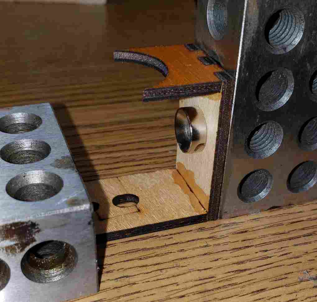
| I used
1, 2, 3 blocks
and magnets to hold the sides square while the
glue set.
The reinforcing corner blocks and mirror
were glued next. The black tape held the mirror in place while
the glue dried. The mirror that I used is 1" in diameter (eBay
/
Amazon)
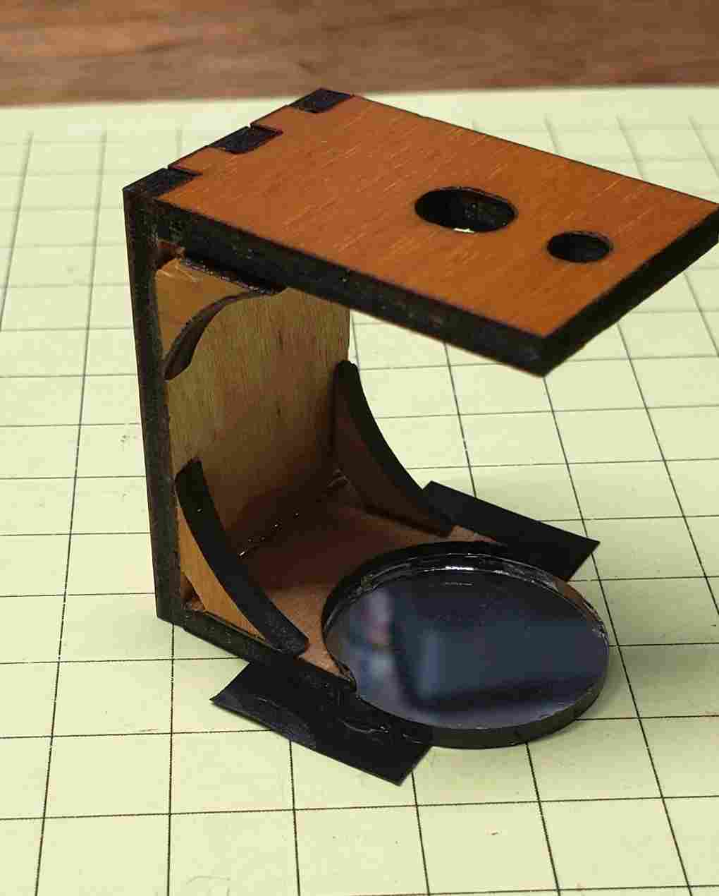
Three parts go onto the top of the sensor, a phototransistor, small laser and 10K resistor.
|
| I glued the phototransistor in first and
set the laser in its hole and applied 5 volts DC to its connecting
wires. I adjusted the laser's position so that its beam
reflected from the mirror and back onto the phototransistor.
Once it was properly aligned a drop of super glue was carefully
added to hold the laser in place. After that dried additional
glue was added to hold it fast.
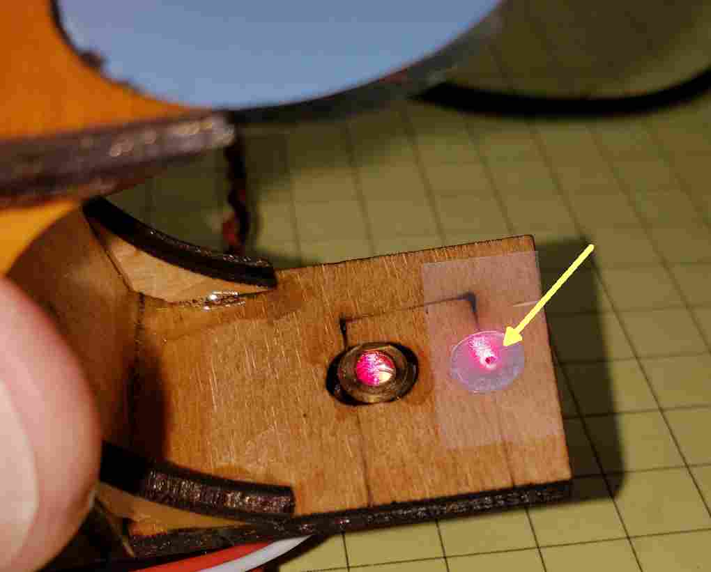
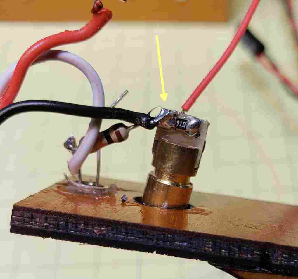
The yellow arrow points to the small circle of aluminum foil with a tiny hole in its center. It is held in place with a piece of clear tape.
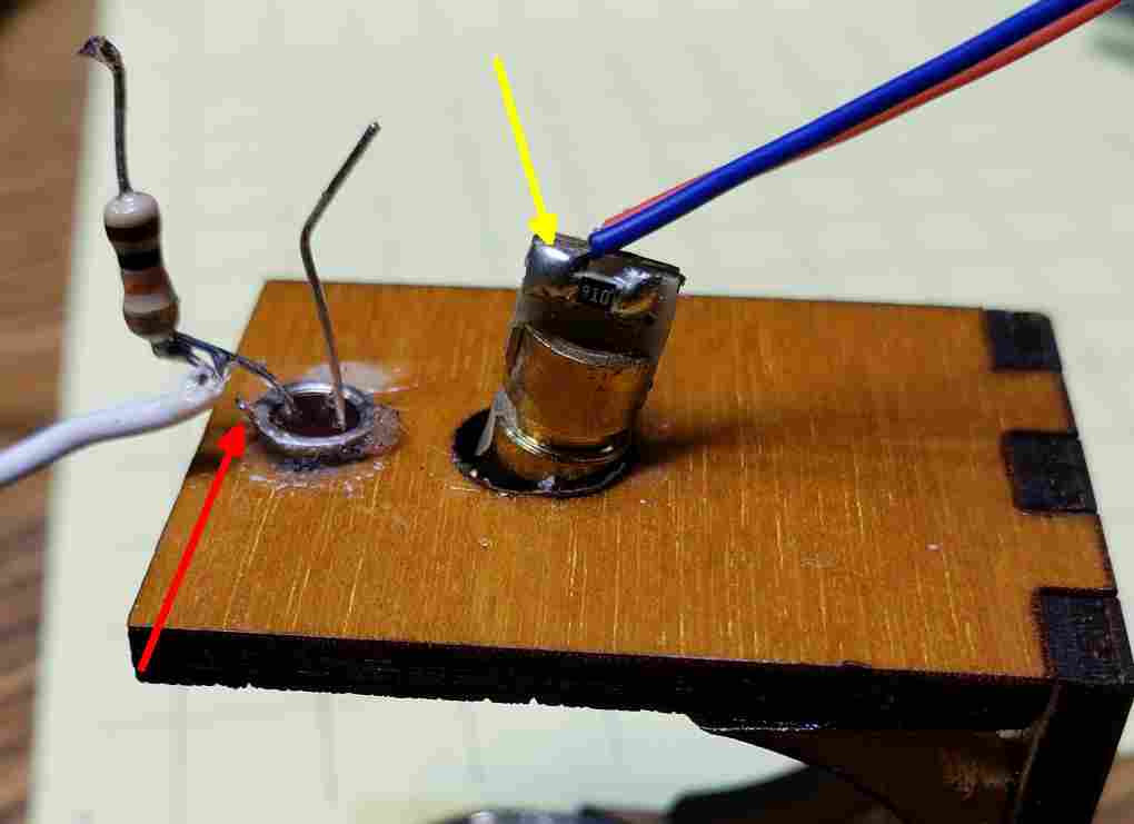
I used a 3 wire servo extension cable to connect to the sensor components. The red wire carries 5 volts DC, the black wire is ground and the white wire is the output of the phototransistor that shows when the beam is broken. When inserting the phototransistor make sure that you put the tab (see red arrow) as shown and, if it is supplies, cut off the middle wire - you only need the wire by the tab and the one opposite it. The laser should be oriented so that the resistor (by yellow arrow) is as shown. Unsolder and remove the blue wire. Note that the 10K resistor has been soldered to the emitter of the phototransistor.
The 10K resistor connects the wire by the
tab, the collector, to the negative terminal on the laser. The
black servo wire goes there, too. This close-up shows the wiring on the positive side of the laser. It connects to the red servo wire and the collector (wire opposite the tab) of the phototransistor. This photo also more clearly shows the wire to be clipped off on the phototransistor (blue arrow) and the tab on the phototransistor (yellow arrow).
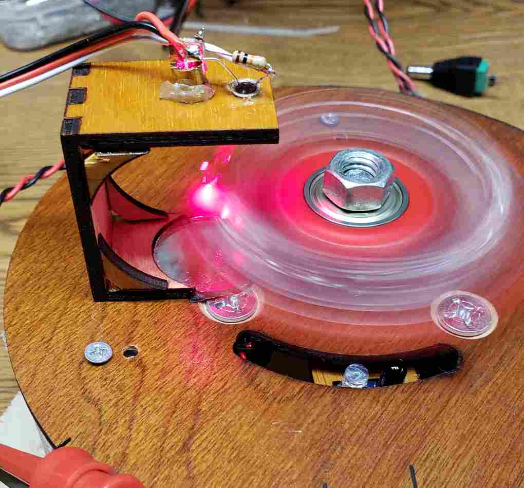
Here the sensor is in place. You can clearly see the laser's beam bouncing off of the fidget spinner as it rotates.
|
|
|
| The Arduino Software The sketch is shown here. It uses an interrupt routine to record each break of the laser beam. These readings are averaged and the resulting rotational speed is displayed on an LCD display. |
// Revised 10-11-2018  d. bodnar  version 2.4
//Based on code found here:  http://www.pyroelectro.com/tutorials/tachometer_rpm_arduino/software.html
#include <LCD.h>
#include <Wire.h>
#include <LiquidCrystal_I2C.h>
#define I2C_ADDR    0x27 // <<----- Add your address here.  Find it from I2C Scanner
#define BACKLIGHT_PIN     3
#define En_pin  2
#define Rw_pin  1
#define Rs_pin  0
#define D4_pin  4
#define D5_pin  5
#define D6_pin  6
#define D7_pin  7
LiquidCrystal_I2C  lcd(I2C_ADDR, En_pin, Rw_pin, Rs_pin, D4_pin, D5_pin, D6_pin, D7_pin);
unsigned long time;
int rpm = 0;
volatile float timer = 0;
volatile float time_last = 0;
volatile int rpm_array[5] = {0, 0, 0, 0, 0};

void setup()
{
  Serial.begin(9600);
  //Digital Pin 2 Set As An Interrupt
  attachInterrupt(0, FidgetSpinner_interrupt, FALLING);
  lcd.setBacklightPin(BACKLIGHT_PIN, POSITIVE);
  lcd.setBacklight(HIGH);
  lcd.begin(16, 2);
  lcd.print("Current Speed is");
  Serial.println("VERSION:  FS_Tachometer_interrupt_v2-4");
  time = millis();
}

//Main Loop To Calculate RPM and Update LCD Display
void loop() {
  if ((timer >= 700000) || (millis() - time >= 1000) ) rpm = 0; // needed to zero display when going very slowly
  delay(500);
  lcd.setCursor(0, 1);
  lcd.print("                "); // clear bottom line
  lcd.setCursor(0, 1);
  lcd.print(rpm);
  lcd.setCursor(6, 1);
  lcd.print("Rev/Minute");

  if (timer > 0) {
    //Average the last 5 readings to help smooth out the displayed speed
    rpm_array[0] = rpm_array[1];
    rpm_array[1] = rpm_array[2];
    rpm_array[2] = rpm_array[3];
    rpm_array[3] = rpm_array[4];
    rpm_array[4] = 60 * (1000000 / (timer * 3)); // three lobes on fidget spinner
    rpm = (rpm_array[0] + rpm_array[1] + rpm_array[2] + rpm_array[3] + rpm_array[4]) / 5;
  }
}

//Interrupt routine to detect laser beam breaks
void FidgetSpinner_interrupt()
{
  timer = (micros() - time_last);
  time_last = micros();
  time = millis();
}
|
| How Fast is the Outside Edge of the
Fidget Spinner Going? The fidget spinner has a radius of 1 5/8" - the diameter is 3.25" @ 5000 rpm the outer rim of the spinner
goes 5000 x circumference = |
