A Better Constant Brightness Circuit for LEDs
Revised 02-05-10 updated 11-2012
Addendum Added 11-15-2012

Introduction

A few years ago I wrote an article, A Simple Constant Brightness LED, that described a circuit that could be used to illuminate an LED to full brightness over a range of voltages.  Since then technology has continued to advance.  I recently came upon a new solid state device that takes much of the guess work and computation out of the equation when we use LEDs.

This new electronic component is designed specifically to drive LEDs.  Before we delve into its characteristics and use it might be wise to review how LEDs operate and the "rules" one must follow to keep burning brightly for many, many years.

The Rules

1.  LEDs require a minimum voltage to create light.  This voltage can vary with LED color and generally ranges from 2 - 3 volts.  This is called the LED's "forward voltage".  Note that this is a minimum.  Higher voltages can be used so long as one adheres to rule #2.
2.  LEDs are current driven devices.  Once the minimum forward voltage is delivered (Rule #1) the LED will light.  Its brightness will be determined by that voltage and the amount of current that it is allowed to consume.  The higher the current delivered the brighter the light... up to a point.  If too much current is allowed to flow the LED will quickly heat up and be destroyed.  Most general purpose LEDs operate well at 20 ma, 0.02 amps.  That is a very small amount of current and explains why LEDs deplete batteries so slowly.
3.  LEDs operate from direct current, DC, and have two leads, a cathode and an anode.  The cathode connects to the negative power connection and the anode to the positive.  The anode is generally the longer lead.  The cathode frequently extends from the notched side of the LED and is shorter.


If you follow these rules you should get good service from your LED lighted equipment.  Stray from them and you are likely to see how quickly an LED can be destroyed! 

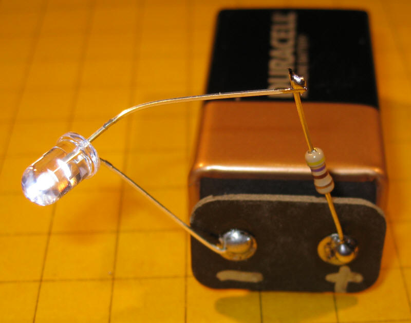
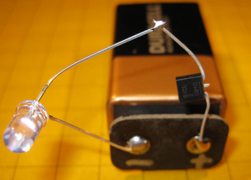
Limiting Current

The most common way to limit the current that is allowed to flow through an LED is to place a resistor in series with the LED and its power source.  A number of methods of determining the value of this resistor are explored in the LED article referenced above.  Typical values range from 100 ohms to 1000 ohms depending on the LED and the voltage that is being used.  This is one of the problems with limiting current with resistors, the higher the voltage the higher the resistance must be. 

This photo shows a very simple LED circuit composed of an LED, a 470 ohm resistor and a common 9 volt battery.  Note that the resistor is connected to the positive terminal on the battery and to the anode on the LED.  Even though it makes no difference which lead of the LED you connect to the resistor I have gotten into the habit of always putting the resistor on the anode side of the LED.  That way I can tell at a glance which lead goes to positive and which goes to negative.

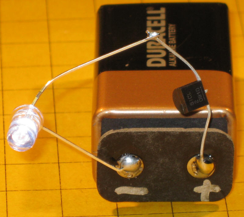
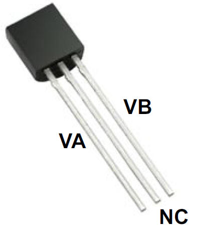
A Better Solution

LEDs have become so common in our homes, consumer electronics and automobiles that it is not surprising that an integrated circuit has been developed that is aimed specifically at driving LEDs.  This device is the CL2N3-G LED Driver from Supertex.  It is inexpensive, even in small quantities, and is configured to deliver a constant current of 20 ma to an LED.  The CL2N3-G can be ordered from Mouser Electronics for about $0.44.   There is also a similar IC that delivers 25 ma, the CL25N3-G.

The CL2N3 couldn't be easier to use.  Just insert it in series with the DC power source and the LED.  The TO-92 package has three pins but only the outside two are used.  The center pin can be cut off.  The positive voltage goes to pin VA and pin VB goes to the anode of the LED.  Remember, the center pin, labeled NC, is not connected.


CIRCUITS
The simplest circuit utilizing the CL2N3 is shown below.  The amazing thing about this device is that the battery, or other DC power source, can be as high as 90 volts and the LED will still see only 20 ma.

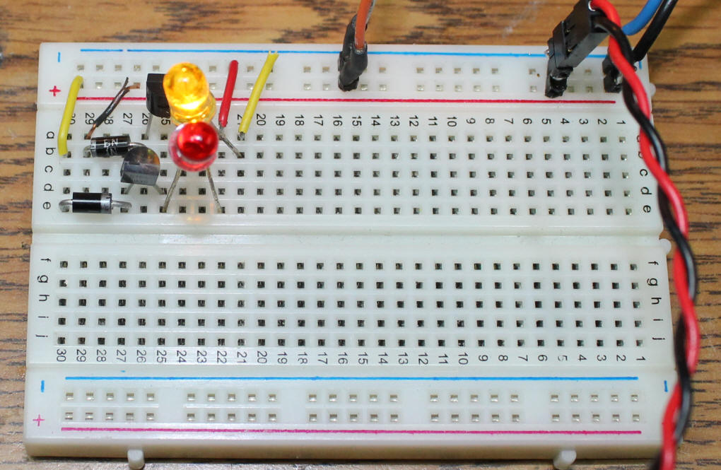
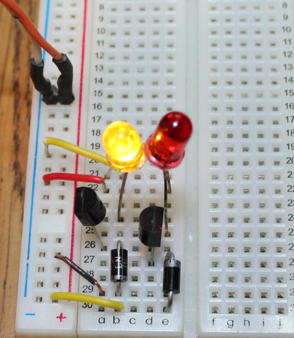
Here is a photo of the same circuit.  Notice that the center lead of the LED driver has been cut off.


LEDs in Series
You may recall from one of my earlier articles on LEDs that they can be wired in series (see:
LEDs 101 - The Basics).  The beauty of using LEDs in series with the CL2N3 is that you do not need a current limiting resistor.  All of the LEDs in the series will get 20 ma and all will light so long as the voltage supplied is high enough to deliver the required forward voltage to each LED.  For example, if each LED requires 2.2 volts to light and you are putting six of these LEDs in series the voltage must be at least 6 x 2.2 or 13.2 volts.  Any voltage at or above 13.2 will work.  If your batteries  supply 20 volts you could have as many as 9 of these LEDs in series.  What a great way to illuminate the interior of a passenger car.

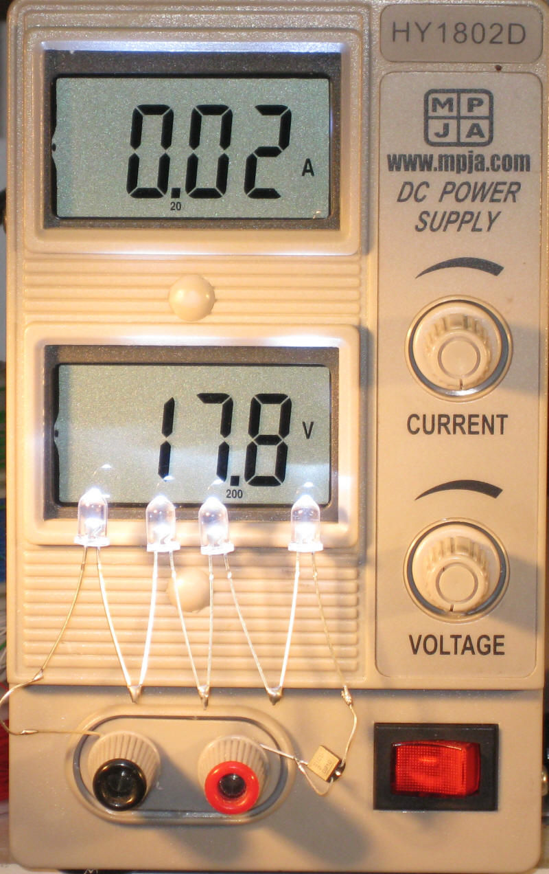
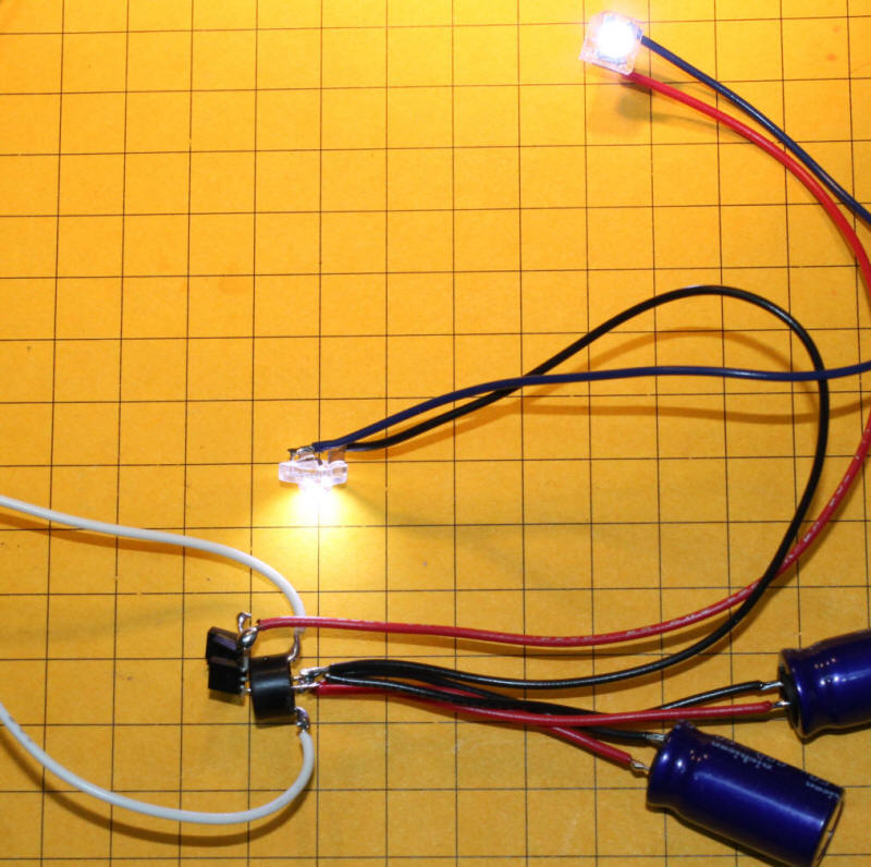
Here you can see four LEDs wired in series along with a single CL2N3. The circuit is powered by a bench power supply that is supplying 17.8 volts, shown on the bottom display.  The top display shows that the circuit is drawing 0.02 amps or 20 ma, just as we would expect.


CL2N3s in Parallel
The CL2N3s can be wired in parallel should you want to supply more than 20 ma to your LED.  This might be done if you were working with higher output LEDs like those that I used for the head lights for
Mr. Rogers Trolley.  Each of those extremely bright LEDs drew 60 ma.  To safely drive them this circuit could be used:

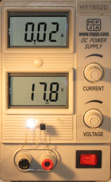
The next three photos show a 1/2 watt LED connected to 17.8 volts.  The first photo shows this circuit with a single  CL2N3.  The meter tells us that 0.02 amps is being supplied to the LED.

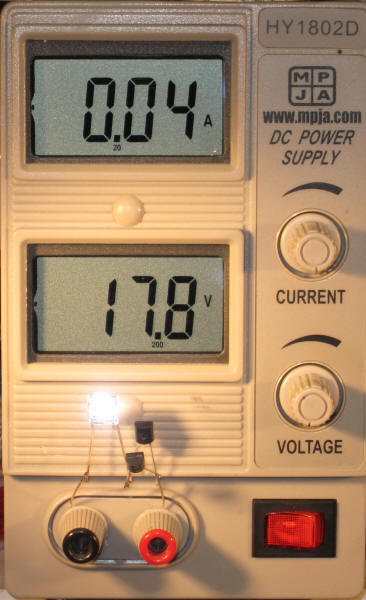
Here a second CL2N3 has been added to the circuit.  It is wired in parallel with the first LED driver.  The meter shows that 0.04 amps is being supplied as we would expect.  Although it is difficult to see in the photo the LED is also considerably brighter.

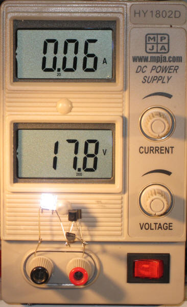
The last photo in this series shows three CL2N3's in parallel and 0.06 amps going to the LED allowing it to achieve its full brightness.


Conclusion
I think you will agree that the CL2N3 makes it simple to manage the use of LEDs.  I encourage you to give them a try with your next lighting project.  Please let me know if I can help!


Update - 9-2011

This circuit is designed to power two bright "flux" LEDs that will be installed inside of spotlight housings.  It uses a bridge rectifier to change the track power to constant polarity.  There are three CL2N3 ICs wired in parallel that limit the current to 60 ma.  The two LEDs are wired in series so that one set of CL2N3's can power them.

There are also two small capacitors wired in parallel with the output of the bridge rectifier that will help to keep the LEDs from flickering.

This close-up shows the bridge rectifier and the three CL2N3's.  Track power is connected to the two white wires.

Addendum 11-15-2012

A question came up recently about how to use two LEDs that would act as front and rear lights on a locomotive wired so that one lit when the power had one + / - orientation and the other lit when the polarity was reversed.  The schematic below shows one way of doing this with the CL2N3's

Here is a photo of a bread boarded circuit.  I ran this with several high-amperage motors and it worked perfectly without the LEDs being damaged.

The power comes in through the Black / Red wires.  The Blue / Black and Orange / White go to two motors.  You will note that the bread board is slightly different from the schematic with the diode and LED swapped on one section.  The two wiring methods are functionally identical.