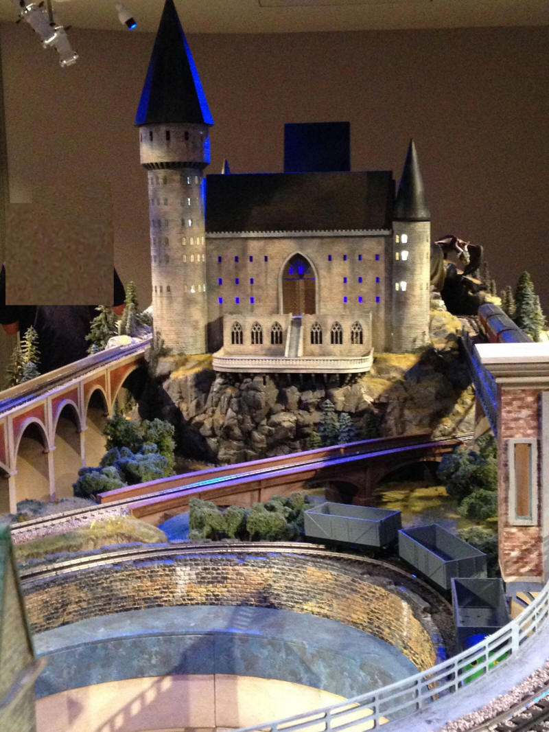
Children's Hospital of Pittsburgh has a wonderful O-scale train layout that represents scenes from the Harry Potter movies. There is a large castle at one end of the layout and I wanted to add an animation to the castle that would flash bright LEDs in concert with an audio track of claps of thunder.
I have a good deal of experience with micro-controller controlled MP3 players including the VMUSIC2 and the DFPlayer. I opted to use the DFPlayer for this project as it works very well with an Arduino and is quite inexpensive. More importantly it is easy to control and can power a speaker without an additional amplifier.
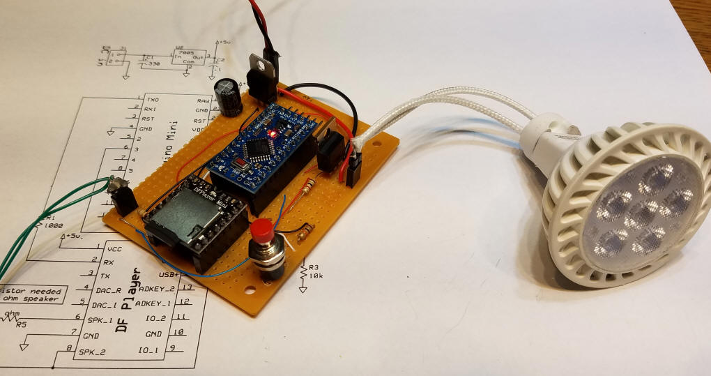
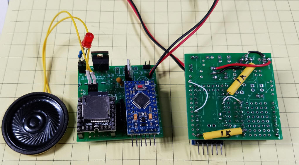
This project can be built on a piece of prototype board with point to point wiring. Add a bright LED bulb or three and a speaker to the Arduino and DFPlayer and you are ready to go!
In addition to the DFPlayer and an Arduino I needed a Mosfet (an IRL520) to drive a group of LED lights that operate from 12 volts and can draw a good bit of current. I have tested the unit with as many as 4 six LED spotlight bulbs wired in parallel.
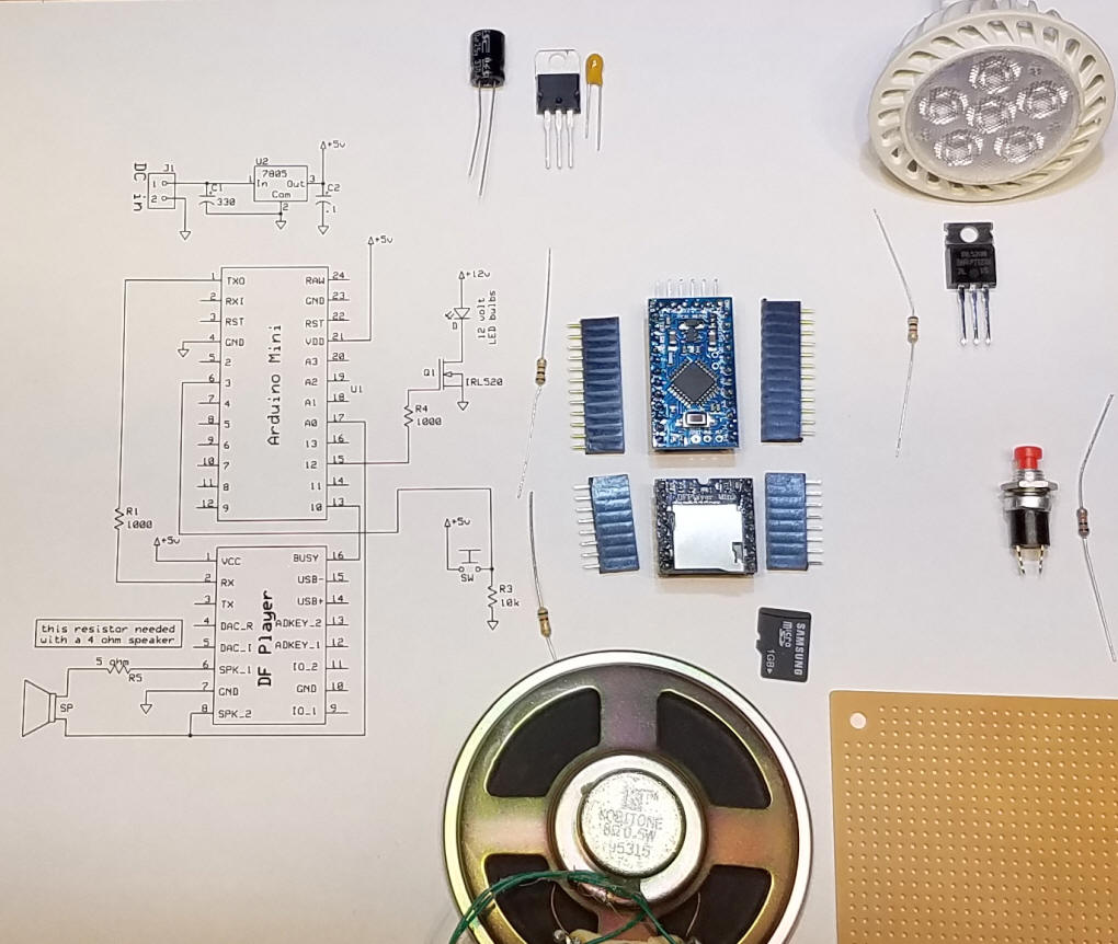
The schematic is here:
The DFPlayer's RX pin is connected to the Arduino's TX pin. Be sure to include the 1000 ohm current limiting resistor. Pin 16 on the DFPlayer (busy) goes to pin 10 on the Arduino - that allows the Arduino to know if the MP3 file is playing or not.
The bright LED spotlight bulbs are connected to the Arduino through a Mosfet, Q1, which turns the lights on and off. This behavior is made possible by the connection between speaker pin 8 on the DFPlayer and analog pin 0 (zero) on the Arduino. The sound is sampled continuously and, when a loud sound is detected, the bulbs light brightly. When the sound subsides the LEDs go off.
Parts:
- Arduino Pro Mini - the Arduino Uno will work, too.
- DF-Player (must be labeled DF Player - there are many similar units that will not work)
- micro SD card - 1 gig is plenty
- 7805 voltage regulator
- heat sink for regulator
- IRL520 Mosfet
- 10 uf / 25 volt tantalum capacitor (anything from 1 to 10 uf will work)
- 470 uf / 25 volt electrolytic capacitor (anything from 220 - 1000 uf will work)
- 8 ohm speaker (junk box or old computer speakers -If you use a 4 ohm speaker R5 is needed - see schematic)
- 1 or more LED spotlight bulbs - the ones I used have six LEDs in each bulb and are VERY bright!
- sockets for the LED bulbs
- pushbutton "start" switch (any momentary SPST switch will work)
- female 2.54mm header (to cut up for the Arduino and DFPlayer sockets)
- miscellaneous connectors, wire, etc
- 10 K resistor (1)
- 1 K resistor (3)
- 12 volt 2 amp power supply
- Circuit board for prototype construction (approx 2" x3")
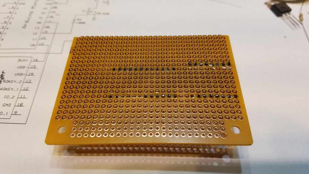
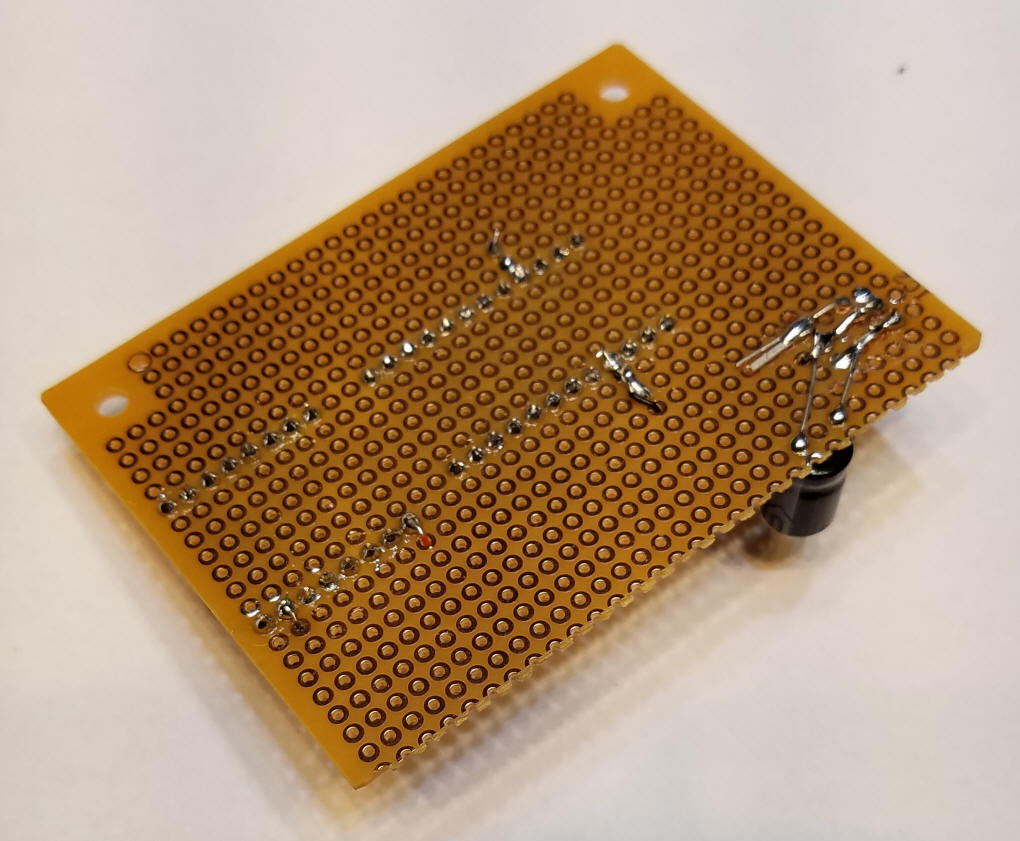
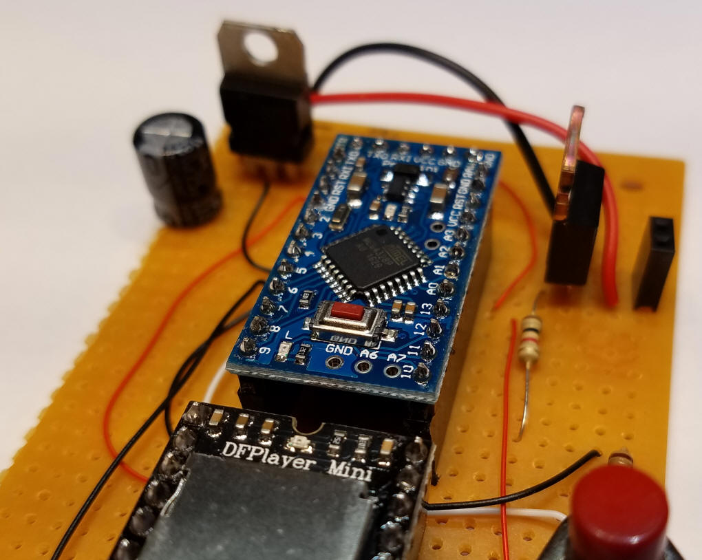
The unit was built on a small piece of prototype board. The solder pad side of the circuit board faces down and the components are inserted from the other side.
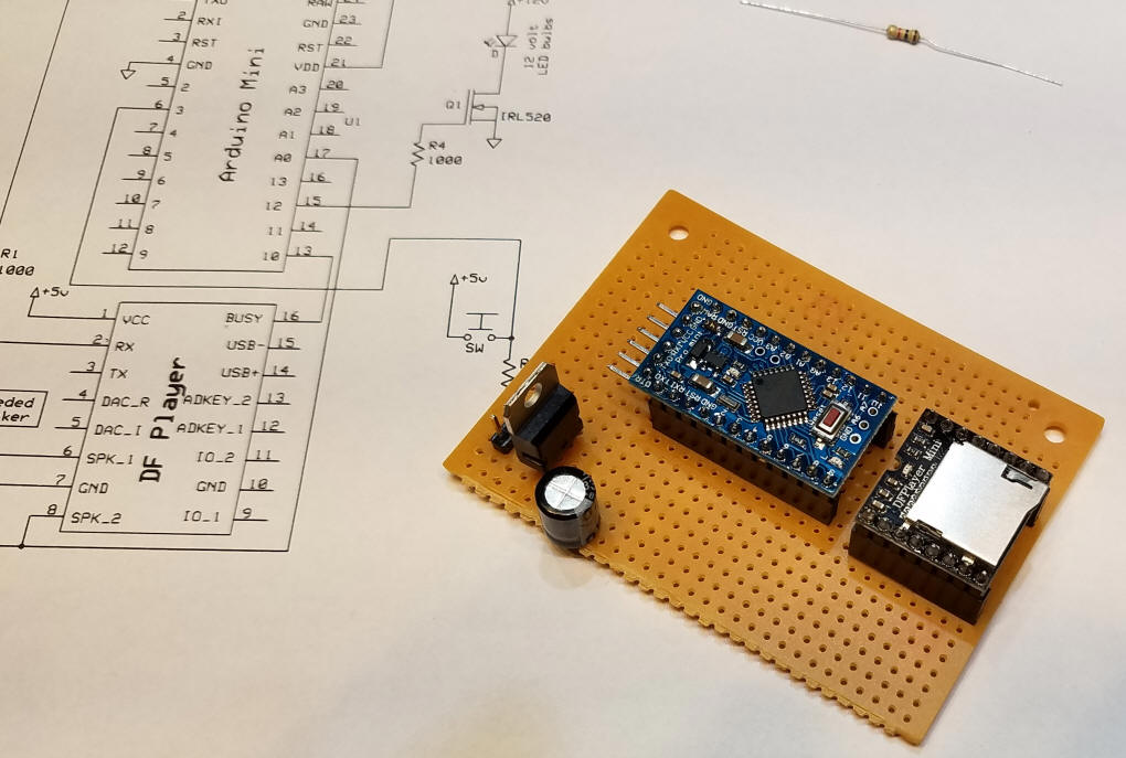
Step 1 - solder the Arduino and DFPlayer to the board using female header sections.
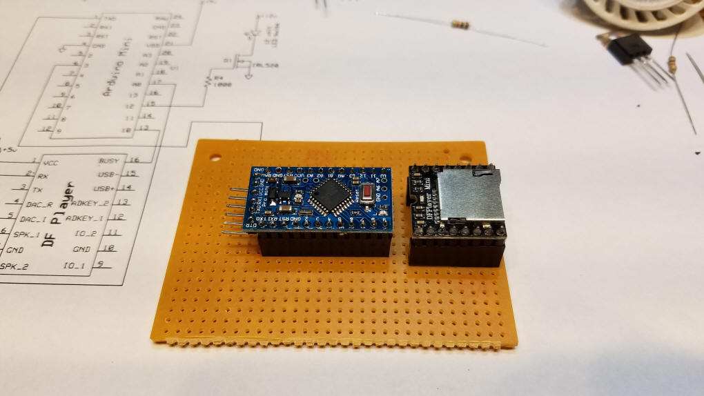
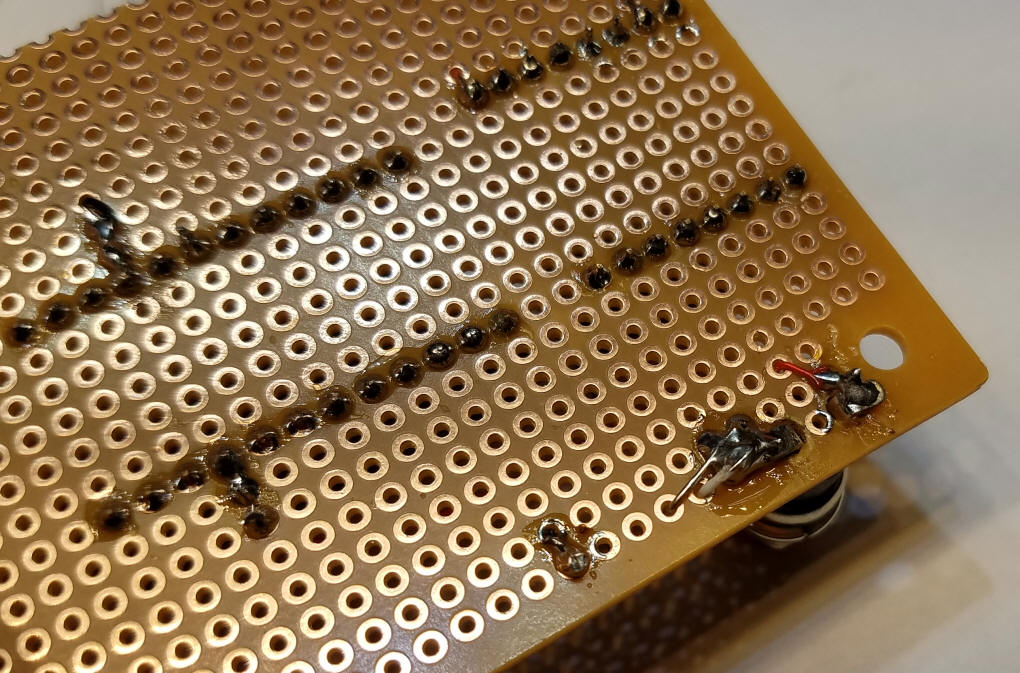
Be careful that there are no solder bridges connecting adjoining pins.
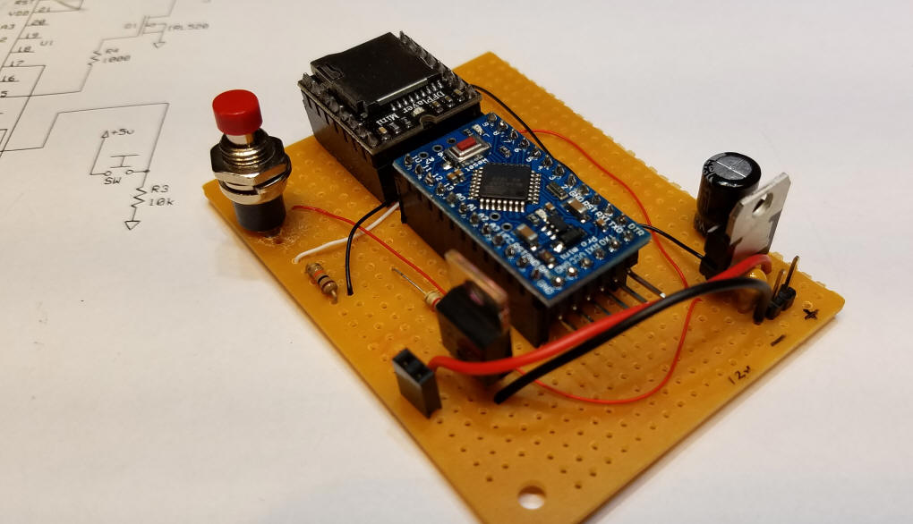
Step 2 - power supply
The 7805 voltage regulator and the two capacitors are added next - the tantalum capacitor cannot be seen in this photo - it is on the other side of the 7805.
Again, be careful of solder bridges!
Next add the wires that supply +5 volts (the red wires) and ground (black wires) - the two wires that are not connected will be used for the "start" switch.
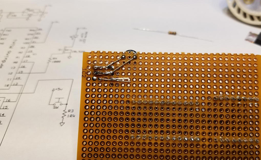
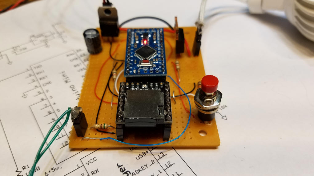
Step 3 - add the "start" switch
To accommodate the switch that I used two 1/8" holes were drilled in the board. The 10 K resistor holds the Arduino pin that connects to the switch low until it is pressed.
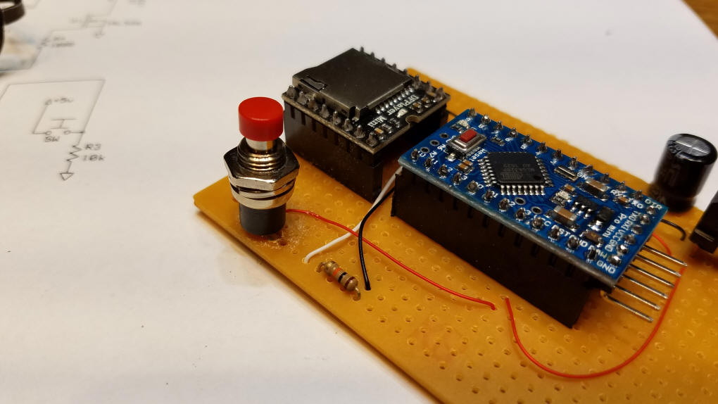
Step 4 - add the light control Mosfet - there is a two pin female header next to it that the LEDs plug into - if you prefer they can be wired directly.
The two heavier red and black wires deliver power directly to the Mosfet and the plug for the LED bulbs. Using thinner wire would limit the amount of current available to the LEDs.
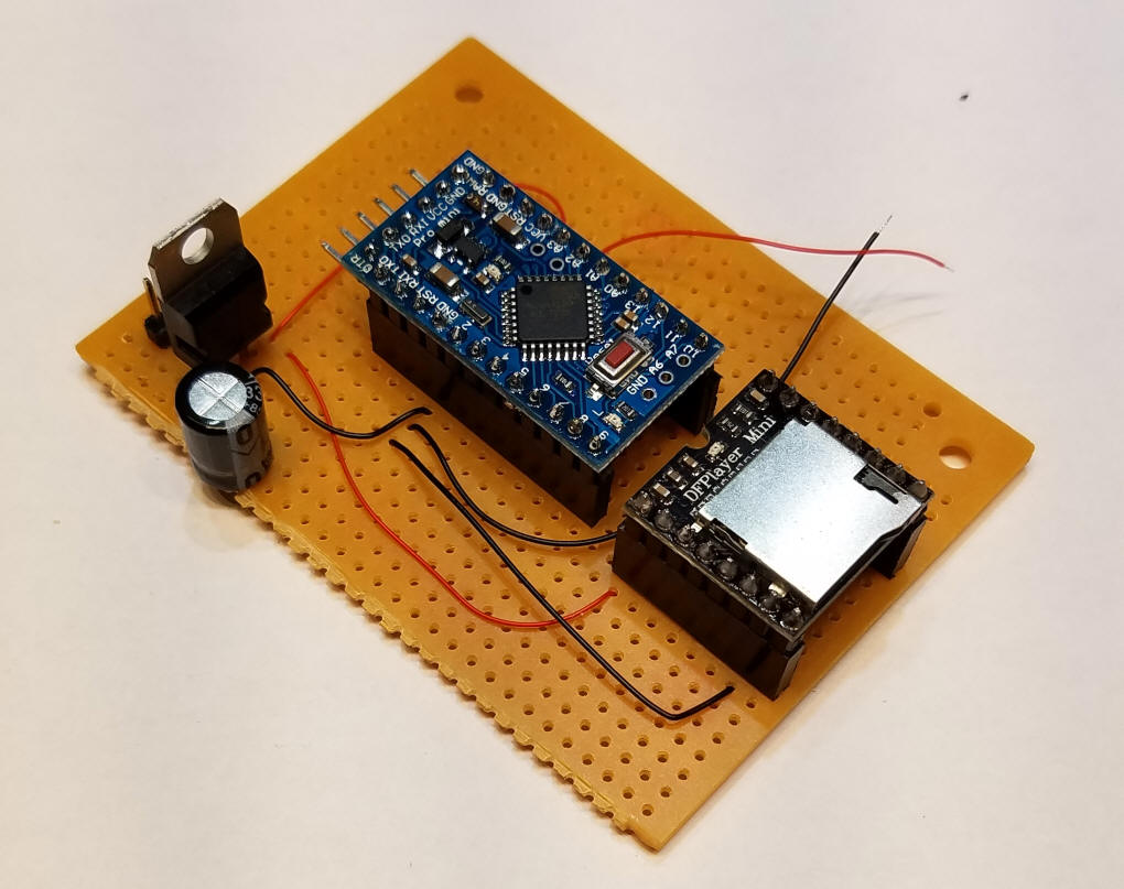
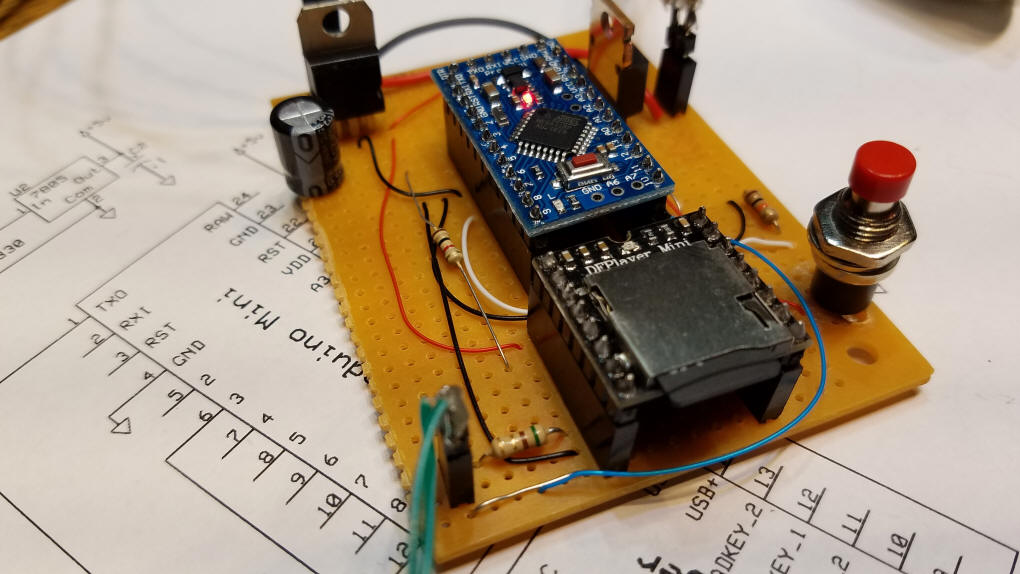
Step 5 - final connections
Don't forget the jumper between Arduino pin 10 & DFPlayer pin 16 and the wire (blue in the photos) that connects speaker pin 8 on the DFPlayer and pin A0 on the Arduino. The 5 ohm resistor between the speaker and pin 6 on the DFPlayer is only needed if you use a 4 ohm speaker - if you don't use the resistor with a 4 ohm speaker the voltage regulator will get quite hot. An 8 ohm speaker works without the resistor.
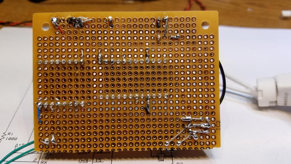
The wires on the top of the board were placed that way to more clearly illustrate the circuit wiring. If you prefer you could put those wires on the bottom of the board.
The wiring on the back of the board is minimal.
You can download the thunder sound files by clicking here. On your Micro SD card place them in a folder called mp3
The sound files themselves are numbered 0001.mp3, 0002.mp3 and so on. I only use 0001.mp3 in the video.
The Arduino code shown here . There are two variables ( if (sensorValue >= 750) { and if (sensorValue <= 666) { ) that can be adjusted based on your sound files - 750 is the analog reading that triggers the LED strip light on and 666 is the level where the LEDs are turned off. Since this happens at a very fast rate it does a remarkable job of simulating lightning flashes that are synchronized with the claps of thunder. Watch the video to see how the program works.
The only library ( #include <DFPlayer_Mini_Mp3.h> ) that is used can be downloaded here: https://github.com/DFRobot/DFPlayer-Mini-mp3/blob/master/DFPlayer_Mini_Mp3/DFPlayer_Mini_Mp3.h
If the above library doesn't work give this one a
try:
Animation-thunder-lightning/DFPlayer_Mini_Mp3.zip
--
unzip it into a folder on your PC and add it to the Arduino/Library
folder in your ProgramFiles folder - I have not tried adding it as a ZIP
file so the safer route is the one just described.
|
/* d. bodnar - 9-06-2016 Lightning & thunder for CHP castle */ #include <DFPlayer_Mini_Mp3.h> const int buttonPin = 3; // the number of the pushbutton pin int buttonState = 0; // variable for reading the pushbutton status int buusyPin = 10;// buusyPin = 10; // sound player busy int bsy = 0; int LEDstripLight = 12; // IRL520 to LED strip light int sensorPin = A0; // Audio level samples int sensorValue = 0; // variable to store the value coming from the sensor int buttn = 0; //***************************************SETUP************************************* void setup () { pinMode(buttonPin, INPUT); pinMode(LEDstripLight, OUTPUT); pinMode(buusyPin, INPUT); pinMode(buttonPin, INPUT); Serial.begin (9600); mp3_set_serial (Serial); //set Serial for DFPlayer-mini mp3 module mp3_set_volume (30); // must remove mp3_reset(); to get this to work } //.......................................LOOP................................................ void loop () { Serial.println(""); Serial.println("Waiting for Button Push"); do { buttn = digitalRead(buttonPin); // pins closest to power pins } while (buttn == 0); Serial.println("Button Hit"); mp3_play(1); delay(100); do { sensorValue = analogRead(sensorPin); Serial.print(sensorValue); Serial.print(" "); if (sensorValue >= 750) { Serial.println("large number! "); digitalWrite(LEDstripLight, HIGH); } if (sensorValue <= 666) { digitalWrite(LEDstripLight, LOW); } bsy = digitalRead(buusyPin); } while (bsy == 0); // zero when sound active } //...................................... END LOOP ........................................ |
Conclusion
The videos show quite clearly how well the sound and light flashes are synchronized.  This same circuit could easily be adapted for a mine explosion, a fireworks display and many other lighting effects.
Please let me know how you use it! This video shows a simulated mine explosion that uses the same basic hardware. |